CNC engraving text

Home Model Engine Machinist Forum

Help Support Home Model Engine Machinist Forum:

This site may earn a commission from merchant affiliate links, including eBay, Amazon, and others.

gld

Well-Known Member
HMEM Supporting Member
Joined
Jun 18, 2009
Messages
176
Reaction score
89
Location
Tarkio, Missouri
What feed rate would you CNC 'ers use on these 20 degree v bits? My first attempt finial 0.050" plunge rate 10"per minute. The point broke as soon as it touched the aluminum. Feed rate was set at 30pm. Second attempt finial 0.050" plunge rate 5"pm, feed 15"pm, point didn't last one letter. DOC was 0.015". My spindle max's out just short of 10,000rpm. Before I break any more bits, i thought I would ask for some advice.


https://www.amazon.com/SainSmart-Ge...L&psc=1&ref_=pd_bap_d_csi_pb_allspark_BIA_1_i
 
I am probably the total wrong person to ask :). I have not much (more like no) hands on experience.
This is a link to a speed feed table. I have no relation to this company, other than owning some tools and having the paper catalogue :).

Precision Cutting Tools

I would plunge at 10% of the horizontal feed. (this is very uneducated guessing).

Most production people I asked about single lip V-cutters told me to try text with 2 flute ball endmills, with 0.5 or 0.75 mm radius. (they are cheaper and easier to find here)
cutting_table_ball.jpg

Picture is from same website. I was told, if the spindle is "too slow" lower the feed according to the gap. e.g. If the table requires 20 000 but your spindle only does 10 000 just half the feed given in the table.

Hope that helps, curious if it did.

Greetings Timo
 
What feed rate would you CNC 'ers use on these 20 degree v bits? My first attempt finial 0.050" plunge rate 10"per minute. The point broke as soon as it touched the aluminum. Feed rate was set at 30pm. Second attempt finial 0.050" plunge rate 5"pm, feed 15"pm, point didn't last one letter. DOC was 0.015". My spindle max's out just short of 10,000rpm. Before I break any more bits, i thought I would ask for some advice.


https://www.amazon.com/SainSmart-Ge...L&psc=1&ref_=pd_bap_d_csi_pb_allspark_BIA_1_i
Gary

I have no idea about those particular engraving bits but I have used a tungsten carbide engraving bit with similar geometry with good success on aluminium, stainless steel and titanium.

The particular machine I sued only had a max 3000 rpm spindle. In titanium I had 0.35mm DOC and feed at 100mm per minute and plunged at 50mm per minute.

1st image is titanium 2nd is aluminium and is nicer.

Maybe the problem is the Amazon engraving bits?

DSC_0655.JPG

P1000677.JPG
 
Gary,
Your feeds a DOC are mulch too high for a 0.1 mm tip diameter engraving tool.
I use the same type of cutter quite a bit, but mostly with a 0.2 mm tip diameter and for engraving printed circuit boards, but I have engraved aluminum on rare occasions. I have engraved a few very small PCBs with using a 0.1 mm tip diameter.

The most important thing you have to consider is the chip load per tooth at the tip. It needs to be roughly proportional to the tip diameter. So to put things in perspective compare your cutter to a 1/16 inch diameter 2 flute end milling cutter. The 1/16 inch cutter is about 15 times the diameter and has twice as many flutes. this means you need to use a feed rate of approximately 1/30 of what you would use for the 1/16 2 flute end mill. This is a pessimistic value as the single flute cutter has more support behind the tip. Note that if you use a cutter with a tip diameter twice as large you can double the feed rate.

Next com,pare the depth of cut. Your 0.015 inch DOC would compare to using a 1/16 end milling cutter with a DOC of over 0.200 inch. Actually this even a more pessimistic number as the engraving cutter is tapered so the effective DOC can probably 1/2 of this. For engraving I find that engraving any deeper than 1.5 times the tip diameter gains nothing, especially if you are going to fill the engraving with a solid paint such as Lacquer Stik.

In the following photos the engraving cutter had a tip diameter of 0.2 mm. Spindle speed 10,000 RPM. The switch box was engraved (from memory) with both plunge and linear feed rates of 4 IPM. The material was in6061 aluminum that had been primed and painted black before engraving with a DOC of 0.008 including the paint. The letters were filled with white Laquer Stik after engraving., The letters 3/16 height.
The PCBs are 0.047 glass epoxy with 0.002 thick copper. Engraving speeds were 5 IPM with a DOC of 0.005.
Gail in NM
IMG_2166.JPG
IMG_2147.JPG
 
Last edited:
What feed rate would you CNC 'ers use on these 20 degree v bits? My first attempt finial 0.050" plunge rate 10"per minute. The point broke as soon as it touched the aluminum. Feed rate was set at 30pm. Second attempt finial 0.050" plunge rate 5"pm, feed 15"pm, point didn't last one letter. DOC was 0.015". My spindle max's out just short of 10,000rpm. Before I break any more bits, i thought I would ask for some advice.


https://www.amazon.com/SainSmart-Ge...L&psc=1&ref_=pd_bap_d_csi_pb_allspark_BIA_1_i
 
Gary

I have no idea about those particular engraving bits but I have used a tungsten carbide engraving bit with similar geometry with good success on aluminium, stainless steel and titanium.

The particular machine I sued only had a max 3000 rpm spindle. In titanium I had 0.35mm DOC and feed at 100mm per minute and plunged at 50mm per minute.

1st image is titanium 2nd is aluminium and is nicer.

Maybe the problem is the Amazon engraving bits?

View attachment 141592
View attachment 141593
Hi Gary , I use a .250 dia carbide 2 flute mill drill, with a 60 deg point angle. I do most of my engraving in aluminum, 9000 rpm at 5.0 ipm plunge and a conservative 10.0 ipm feed rate. The depth is .024 for most text. If you want wider text use a .250 dia carbide 90 deg
point mill drill, same plunge same rpm and feed rate and same depth. This will give you wider text. I have found these values to be a starting point. Adjust the #s for steel, etc.Magicman said this.
 
I used the same 60deg 0.3mm cutters to make some name plates for my Wyvern. I used 7000rpm which is the highest speed available. I used a depth increment of 0.1mm. This is low but the cutters are fragile!
The total depth was 0.6mm in brass sheet 1.5mm thick glued to a AL support sheet. Lubrication was by cutting oil applied using a small brush which also ensured that the chips were removed. An air jet would have been better I think but was never tried. The outline shape and hole positions were in AutoCad and imported as a DXF into CamBan. I used the text function in CamBan to generate the area clearance and generate the Gcode. Took about 10 hours to machine! The final name plate was sand (glass) blasted and the top surface polished
Wyvern Name Plate in brass.jpg
1666786979487.png
 
I used the same 60deg 0.3mm cutters to make some name plates for my Wyvern. I used 7000rpm which is the highest speed available. I used a depth increment of 0.1mm. This is low but the cutters are fragile!
The total depth was 0.6mm in brass sheet 1.5mm thick glued to a AL support sheet. Lubrication was by cutting oil applied using a small brush which also ensured that the chips were removed. An air jet would have been better I think but was never tried. The outline shape and hole positions were in AutoCad and imported as a DXF into CamBan. I used the text function in CamBan to generate the area clearance and generate the Gcode. Took about 10 hours to machine! The final name plate was sand (glass) blasted and the top surface polished
View attachment 141645View attachment 141647
Mike
How large is the nameplate, there is no idea of scale.

B.
 
Hello,

made some hands on training today.
K1600_P1010037.JPG

Official depth of cut is 0.03 mm but I would trust it by +-0.01 mm.
The complete text box is about 45 mm x 20 mm. (1.7" x 0.75") and the indivitual letters about 4 mm high.
Material is unhardened tool steel: 5000 rpm, 100 mm/min or 10 000 rpm 200 mm/mm. Plunge speed 10 mm/min.
On the result I cannot tell were I switched the speeds.

(Took about 9 min, quite lame ;), but the cutter is still alive)

Greetings Timo
 
A ball cutter will certainly be more durable as there is a lot more material to back up the cutting edges, this quick sketch shows the cut mentioned above by Timo on the right compared the the Shape of the cutter in the opening post both at 0.03mm depth. The ball nose gives a cut width 5times wider which can be a problem on small or light type faces. Also being that muck wider the surface speed is greater.

engrave.JPG


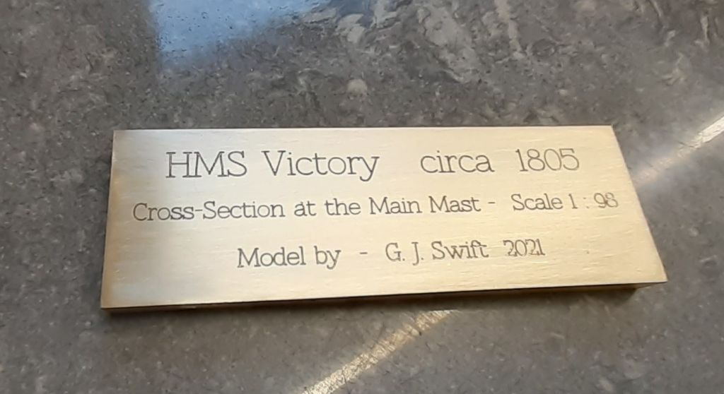
This was done with a 60deg cutter, 0.3mm tip, 0.12mm deep as any more and the letters started to blend into each other. The brass plate is 63mm wide, the mid and lower two lines use 2.5mm text height (for the capitals) and 4mm high for the top row. Speed 5000rpm with 50mm feed.

902237.jpg
 
A ball cutter will certainly be more durable as there is a lot more material to back up the cutting edges, this quick sketch shows the cut mentioned above by Timo on the right compared the the Shape of the cutter in the opening post both at 0.03mm depth. The ball nose gives a cut width 5times wider which can be a problem on small or light type faces. Also being that muck wider the surface speed is greater.

View attachment 141677

This was done with a 60deg cutter, 0.3mm tip, 0.12mm deep as any more and the letters started to blend into each other. The brass plate is 63mm wide, the mid and lower two lines use 2.5mm text height (for the capitals) and 4mm high for the top row. Speed 5000rpm with 50mm feed.
One thing I understand from your sketch. The flatness and height of the work surface becomes more critical when using a ball cutter.

Greetings Timo
 
Yes as you would soon get a proportionally much wider cut if the top surface had not been skimmed flat first.
 
Thanks for all the replies. Got-R-done.

normal_20221026_160851.jpg


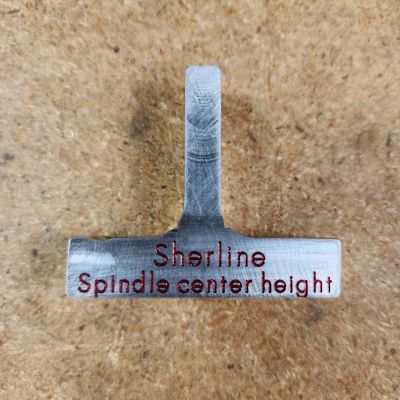
As yo can see ,I made a center height gauge for my Sherline lathe. Wanted to make sure that piece did not get returned back to the scrap bin.

Plunge rate 1 ipm, feed 2.5 ipm doc 0.003. Filled with red Dykem.
 

Latest posts

Back
Top