Chevron Axial V-10 Engine

Home Model Engine Machinist Forum

Help Support Home Model Engine Machinist Forum:

This site may earn a commission from merchant affiliate links, including eBay, Amazon, and others.

Captain Jerry

Project of the Month Winner!!!
Project of the Month Winner
Joined
Dec 2, 2008
Messages
971
Reaction score
9
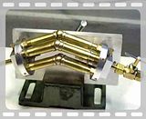
This is not my first engine and hopefully not my last. This design consept began to form in my head several years ago but at the time, I didn't have the tools required to produce it. Even after I got a small lathe (Unimal SL) it was several years before I had conquered all of the design issues and actually got it together. It doesn't make much sense as a power source. I haven't figured out a good means of power takeoff, but for It scores high in scratch-your-head and gawk.

I just joined this forum and this is the first video posting that I have attempted. Hope it works

Jerry


1194
 
Welcome to the forums. That's a neat engine, like an elbow engine but with a 45 degree bend instead of 90 degrees.
Was it hard to get running?
 
:bow: :bow: :bow:

Wow that's brilliant Jerry
You have found yourself a new home here, That's just the kind of stuff we love especially with video.
First class

Kind regards

Malcolm
 
Getting it to run was really not all that hard. There are two rotary valves, intake in the plate at the right and exhaust to the left (uniflow!) The large unsightly upright screw in the support column allows the timing to be adjusted while it is running by rotating the intake/exhaust tubes which also serve as the valve core.

Alignment of the support columns was more of a problem but by leaving the mounting screws sort of loosey goosey it was possible to get it running, let it find its own alignment and then tightening up.

The offset angle is 36 degrees. It could be any angle but 36 is esthetically in keeping with the 72 degree offset of the 5 cylinders per head.


CJ,

That's remarkable. :bow: :bow:

Did your inspiration have anything to do with hydraulic motors ???

Best Regards
Bob
 
Bob

The inspiration may have come from hydraulic motors. It began as a more conventional wobble plate engine, but I had way to much time to think about it before starting to build. At some point, wrestling with the design of the wobble plate mechanism, it occurred to me that if you put two wobble plate engines back to back they could share the plate. The plate then became a virtual plate and just disappeared. From there, it got turned inside out with external cylinders so the shared expansion chamber would be between the pistons rather than have two expansion chambers share a piston as in the elbow engine. It then got so silly, I had to build it just to confirm my thought processes or lack thereof.

Axial hydraulic motors and pumps are interesting. Particularly the variable displacement pumps used in hydrostatic transmissions and in construction equipment like hydraulic excavators. They get the variable displacement by changing the angle of the wobble plate which changes the piston stroke.

I am building a more conventional wobble plate engine now with stationary cylinders and a conventional output shaft. The thought of making the wobble plate angle variable is always on my mind waiting for an inspiration as to how to bring it off. The geometry gets pretty involved. For now, I am using a fixed angle of 15 degrees (30 degree sweep) but I would like to experiment with different angles.

Jerry
 
Jerry,

Thanks for that. :bow: It sure looks like your thought processes are excellent and confirmed. I just had to ask because it reminded me very much of some of the hydraulic tilt plate motors used in some ships steering gear.

Best Regards
Bob
 
Back
Top