Can someone idenitfy this type of linkage?

Home Model Engine Machinist Forum

Help Support Home Model Engine Machinist Forum:

This site may earn a commission from merchant affiliate links, including eBay, Amazon, and others.
Joined
Sep 29, 2012
Messages
9
Reaction score
1
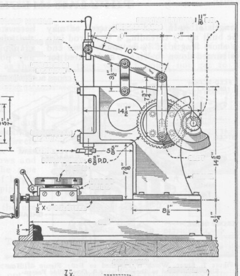
I'm a lurker on this forum, and I need help identifying a linkage system so that I can design a similar one. The picture is from J.V. Romig's article, "Making a Four-Inch Bench Slotter" and is the side view of his designed slotter. I'm interested in the mechanism that turns rotary motion into reciprocating motion. I've looked at and read about 4 bar linkages and 6 bar linkages, and I can see that this is one or the other of these, but I can't figure out which. If someone can identify exactly what type of linkage system this is, I think I can design one that fits my needs exactly.

romig bench slotter by duncanbojangles, on Flickr

To give you an idea of what I'm trying to accomplish, I am also trying to build a small bench slotter. My plan is probably a bit daft, but I've got a 1/2 ton arbor press that I'll use for most of the frame, and I'll beef up the portion that will house the ram. I've got some gears to slow things way down (105 teeth and 28 teeth) and I'm using a purchased X-Y table instead of trying to build my own (though I've got some wonderful linear slides if I do try to build my own).

I'm interested in Romig's mechanism because it turns rotary motion into straight line reciprocating motion over the whole 360 degrees the input rotates, without resorting to slides (other than the ram's motion, but that one is desired. ;)) The slides you do see in the picture are for adjustment of the ram's stroke and position. I've looked at several of the approximate straight-line mechanisms, like Watt's linkage, and Chebyshev's linkage, and the exact straight-line mechanisms, like Watt's parallel motion linkage, but can't find an exact match to Romig's mechanism.

I'm trying to design a similar linkage system in AutoCAD, but not having much luck. I thought I might stumble upon a simple geometric solution, but I don't know enough to even know where to begin. Thanks in advance, and I promise to post build photos if I succeed in building a bench slotter (and maybe even if I don't!).
 
I've given away my old Drummond shaper and relevant books. However, I think that you will find something on the NEMES-S .Org website. I recall that numerous shaper books are there including the one by Ian Bradley which covered my old machine.

Let me know if this has been useful in your search.

Norman
 
.

This is just a variation of a standard 4 bar linkage.
Two vertical and two horizontal bars.

The variation here is that the machine body and the drive gear make up the lower horizontal bar, making that bar variable in length.

An extension of the upper horizontal bar is used to drive the vertical slotter bar up and down.

Looks like this design drawing is from some 1890 machinery book, painfully short of any real useful dimensions, and what dimensions are there are all in that Olde - Worlde dimensioning system :eek:


.
 
That picture is not a true linear output linkage system. If you take away the output ram, the linkage is under constrained, and will not give you linear motion at the output. Say if the middle pivot of the 10inch arm is a fixed point on the frame, the output of that arm will be an arc motion, and if you use that to drive a linear constrained ram, it is just going to bind. That's what the 3.5inch short link is for.
 
That picture is not a true linear output linkage system. If you take away the output ram, the linkage is under constrained, and will not give you linear motion at the output. Say if the middle pivot of the 10inch arm is a fixed point on the frame, the output of that arm will be an arc motion, and if you use that to drive a linear constrained ram, it is just going to bind. That's what the 3.5inch short link is for.
Ahh, thank you Jimmyjo! I could tell that the short 3.5" link was what allowed the long 10" link to drive the ram straight up and down, but wasn't sure exactly what factors defined its length. I did stumble across several references of crank and slider mechanisms, yet I was still stuck looking for mechanisms giving straight line motion. Now I know that I don't need one of those types of mechanisms, and a simple crank and slider type mechanism will suffice.

.

This is just a variation of a standard 4 bar linkage.
Two vertical and two horizontal bars.

The variation here is that the machine body and the drive gear make up the lower horizontal bar, making that bar variable in length.

An extension of the upper horizontal bar is used to drive the vertical slotter bar up and down.

Looks like this design drawing is from some 1890 machinery book, painfully short of any real useful dimensions, and what dimensions are there are all in that Olde - Worlde dimensioning system :eek:


.
Thank you very much Dave-in-England, this information will surely set me on the right path. Yes, this article is old, and the writer assumes quite a bit from the reader. I'm having a hard time turning real, physical devices into their theoretical perfect link representations in my head, but knowing what it's called should make the task a bit easier.

I've given away my old Drummond shaper and relevant books. However, I think that you will find something on the NEMES-S .Org website. I recall that numerous shaper books are there including the one by Ian Bradley which covered my old machine.

Let me know if this has been useful in your search.

Norman
Thanks Norman, I've spent lots of time on the nemes-s.org webiste reading about shapers. I'm fascinated by shapers, slotters, and planers. I'd love to own one of each one day, just for the novelty, but until that time I'll have to make do with smaller, humbler versions of each machine. :)

And before anyone tries to convince me that building my own metal working tools is an exercise in despair, I already know, and I have no illusions about the quality, rigidity, and usefulness of the slotter I hope to build.

In review, the mechanism shown here is a type of four bar linkage, with the ram being linearly constrained (a slider). Excellent, thank you all again!
 
.
It depends on exactly what type of work ( and stroke length ) you want your design of machine to actually do.

The machine in the picture looks to me to have a maximum vertical stroke length of about six inches,

and with the sliding bolt adjustment on the gear, the working stroke length can be right down to

Zero.

If you have Auto-Cad, why not design something simple by using a roller cam working directly on the top of the vertical slide, driven by a reduction gear, and then you can eliminate all that clunky linkage system, and have a stronger, more rigid machine.

Or.. what about a hydraulic ( not air ) cylinder working directly on the top of the vertical slider ?

A six inch diameter cylinder at 80 psi will give over a ton of pressure, much more than that Victorian mangle in the picture, with full and easy control by a pressure and flow regulator valve.

The machine Mr. Romig designed has a maximum stroke of 4 inches, that was a pretty good guess! I never considered a roller cam, but I don't see how I could adjust the length of stroke with a roller cam operating directly on the ram. I could take your idea a bit further, though, and turn the roller cam into a scotch yoke mechanism that operates directly on the ram. This gives me adjustable stroke length, and lowers the number of moving parts considerably.

I have read that the hydraulically operated slotting machines were a pleasure to operate, but I don't know how keen I am on dealing with hydraulics. I would need a pump, a tank, regulator, and valves to change direction of the ram. Sounds like a lot of stuff to buy.

Mr. Romig's design appeals to me because it uses only easy-to-machine revolute joints, has adjustable stroke length and position (that is, I can have a 4" stroke that ends at the table's surface, or a 2" stroke that ends 1" above the table's surface, etc.), and has an exact end of stroke, meaning I can cut right up to a line. I'll not discount any other ideas offhand, though, since anything that makes it more likely for me to complete my project is very desirable!
 
I was going to suggest you look at a Whitworth quick-return mechanism, as normally used on shapers, but googling slotting machine images it would seem that it is not normal on slotters. I find this puzzling. The function of the reciprocating tool is pretty much the same, so why not drive it the same way?
 
Ahh, thank you Jimmyjo! I could tell that the short 3.5" link was what allowed the long 10" link to drive the ram straight up and down, but wasn't sure exactly what factors defined its length. I did stumble across several references of crank and slider mechanisms, yet I was still stuck looking for mechanisms giving straight line motion. Now I know that I don't need one of those types of mechanisms, and a simple crank and slider type mechanism will suffice.
A roller cam could give you adjustable stroke if the wheel it is mounted on provides for adjustment along the radius. The bit problem I see here is that you won't be transmitting a lot of force through most cam follower rollers. In any event look at the mechanism in many die filers.
Thank you very much Dave-in-England, this information will surely set me on the right path. Yes, this article is old, and the writer assumes quite a bit from the reader. I'm having a hard time turning real, physical devices into their theoretical perfect link representations in my head, but knowing what it's called should make the task a bit easier.
This is where old age is a killer, but I'm fairly certain there is a book or two written on four bar linkages. However a quick search on Gutenberg did turn up this work:
Title: How to Draw a Straight Line; A Lecture on Linkages
Author: A.B. Kempe

That is rather old and I'm certain there are far newer references out there. At least something new enough that when I saw the book a few decades ago it looked well modern. The big problem with these linkages is that they get rather complex after a bit.

The other possibility to consider these days, that is a modern approach would be a lead screw and servo arraignment. There was a time when nobody would have ever considered a lead screw in such an application but you can get some awfully big ball screws these days. I work on a number of electric mold machines and I have to tell you they are very reliable even the screws under high stress.
Thanks Norman, I've spent lots of time on the nemes-s.org webiste reading about shapers. I'm fascinated by shapers, slotters, and planers. I'd love to own one of each one day, just for the novelty, but until that time I'll have to make do with smaller, humbler versions of each machine. :)
Shapers are indeed an interesting machine. It is too bad most of them ever made got turned into scrap. As it is versions of the machines are still made, often called key way slotters. These machines are inverted yet again with the ram coming up through the middle of the table.
And before anyone tries to convince me that building my own metal working tools is an exercise in despair, I already know, and I have no illusions about the quality, rigidity, and usefulness of the slotter I hope to build.
Not to be rude but there is nothing to despair and frankly most of the negativity around home built machinery is baloney. Quality is what you put into it effort wise, rigidity is your will lines to design and buy the materials. As for usefulness, people still ask me why I have a lathe, bandsaws, planers, bench grinders and a bunch of other stuff in my cellar. It might not be useful to them but frankly I don't care about them.

I frequent a few wood working sites from time to time and every once in awhile some guy will post questions about building a lathe or some other machine that you can buy in a store. Invariably dozens of people will try to convince him that it is a bad idea using every excuse that can be dreamed up. Sadly the same people have no problem showing off their home built router table. Sometimes people's perceptions of what is difficult is hard to understand.

So to put it simply, the fact that you want to build something is good enough reason to build it.
In review, the mechanism shown here is a type of four bar linkage, with the ram being linearly constrained (a slider). Excellent, thank you all again!


One thing you need to look out for is odd velocity profiles that can be seen at the RAM as the linkages do their thing. The drive mechanisms for shapers are a little more predictable.

If you are interested in old time solutions to this problem, especially in the context of steam engines, visit the Henry Ford Museum. It is a fascinating place. Obviously most steam engines work in reverse. The other obvious similar machine are the old mechanical presses with the big fly wheel. The difference here is that you need power throughout the stroke and not at the last couple of millimeters.
 
Just wanted to let everyone who's offered advice know that I haven't given up! I've spent far too much time reading about approximate and exact straight line linkages, four bar linkages, six bar linkages, kinematics, etc. I've spent just as much time playing with different multi-body simulation programs, with mostly not much luck. (For those curious to try some, I can recommend Silux and Geogebra. Both are free, and Geogebra works on Windows, Mac, Linux, and in the web browser!)

I was nearly to my wit's end and was going to bother the engineer at work for help. In fact, I went as far printing out the image I posted above, and cutting and pasting the pieces onto cardboard so I could at least play with something physical to wrap my mind around. That was very instructive, good old Cardboard Assisted Modeling (aka CAD :) ). I then got a simple model working in Geogebra to test different lengths of links.

The end result? None of the lengths of links are particularly important. As long as the short link (3.5" in the picture) is long enough (to be determined empirically, I suppose) it will take up the "slack" that comes up in the system from having the ram travel in a straight line while the crank travels in a circle (and the con-rod travels along an arc).

Now I can draw a linkage system that has: the maximum ram stroke I plan on using, a sensible amount of short link travelling arc and position (I want the least arc travel and for the link to be about vertical most of that time), and a good lever ratio.
 

Latest posts

Back
Top