Building a V12 crankshaft

Home Model Engine Machinist Forum

Help Support Home Model Engine Machinist Forum:

This site may earn a commission from merchant affiliate links, including eBay, Amazon, and others.

ZAPJACK

Member
Project of the Month Winner
Joined
Nov 1, 2010
Messages
317
Reaction score
663
Location
Nice Côte d'Azur
Hello there,
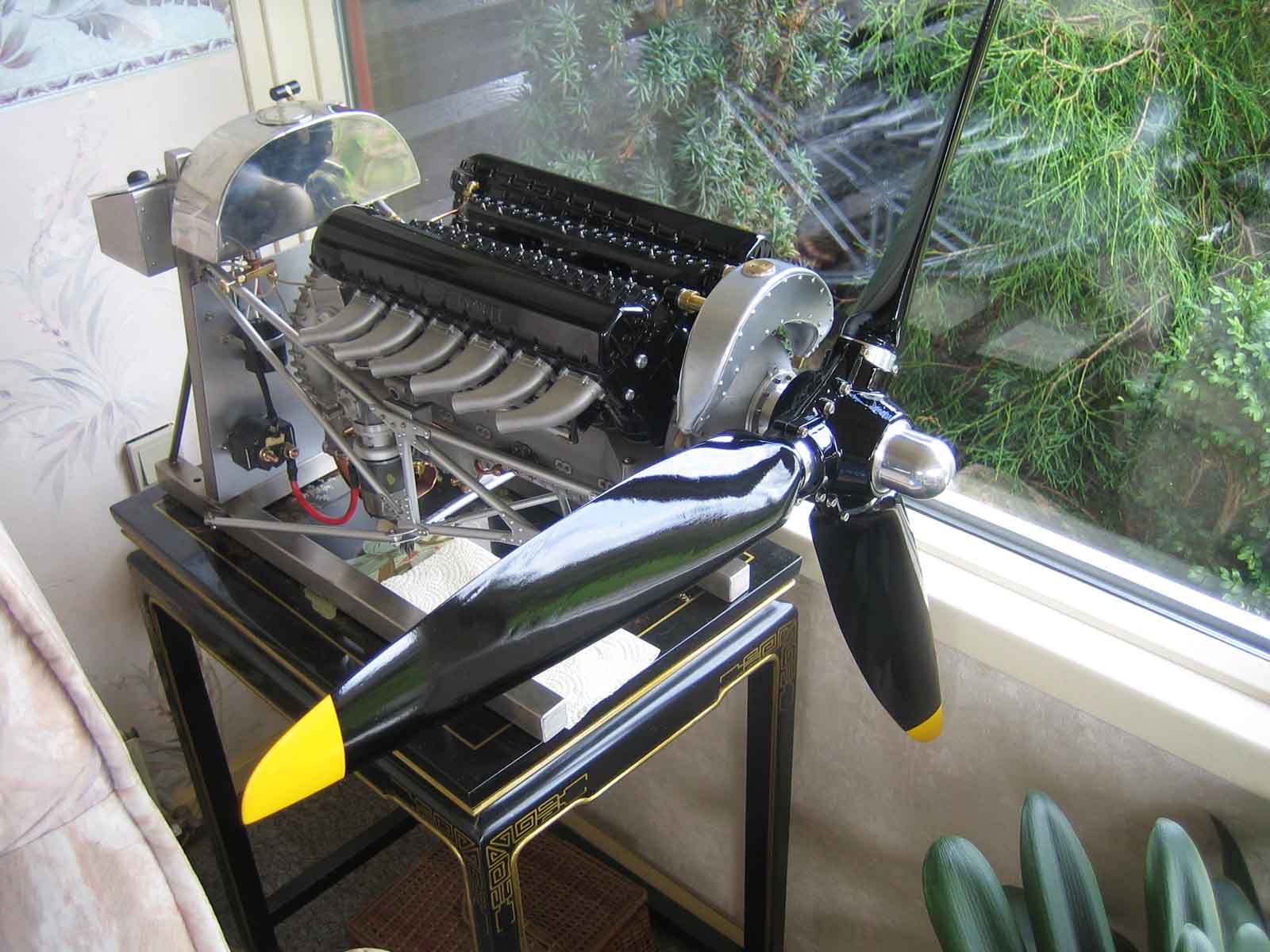
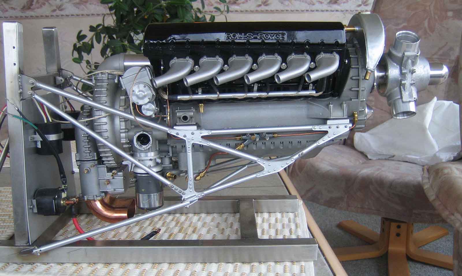
I present to you my last work. It's the crankshaft ot the Rolls-Royce V12 Merlin at scale 1/4.
In the followed weeks, I will post the building process with needed pictures
LeZap

156.jpg


162.jpg
 
WOW! Beautiful work. I don't even like to make more than one of an item. My hat's off to craftsmen like you who can do this kind of work.
 
ZapJack

This looks like it is going to be a very interesting thread. I am sure that there are many that will be following this thread. I look forward to the next instalment.

Cheers :)

Don
 
Manufacturing of a complex crankshaft


First of all I wish to thank all the members of usinages.com and Blooo.fr who gave me advices and opinions in order to succeed in this matter.

I have neither history or work experience in manufacturing and I do not know anybody around me in this art. The methodology and the terminology used can thus surprise sometimes the professionals, thank you for not being irritated against me. However I manufacture by pure passion since 20 years.


The present document may inspire some builders for other works.


The followed process is based on my machines-park and can, of course, be modified with other more performance machines.

This crankshaft is the first step of the construction of the engine Rolls-RoyceMerlin V12 at scale 1/4. Probably the most difficult part to do. www.quarterscalemerlin.com

Datasource: 6 crankpins and 7 journals. Stroke:38.1 mm. Length 266.7mm. 3x 120°

Assembling with two connecting rods per crankpins. Fork assembling.

Selected materials: alloy steel type 34 Cr Ni Mo 6V (GER, BEL) 42 CD 4 T (FRA)

SAE4140 (USA)

It is structural steel to Chromium Molybdenum according to DIN 17200/1013 treated delivered. It allows the manufacturing of torsion bars strongly requested,axes, gears…


Available tools :


  • Schaublin milling machine type 13 of 1964, DRO digitalization Mitutoyo
  • Sinus tilting table, directional milling head, directional fast head with sensitive touch
  • Versatile dividing head & dead center
  • Myford lathe Super7, accessories and collets
  • Micro spray lubrication and Crouzet sequencer
  • Cutting and milling equipments with exchangeable plates
  • Metrology : Tesa, Mahr, Mitutoyo, etc …
 
Last edited:
Hi Le zap. Great looking project. Can you tell us a bit about the Crouzet sequencer. How you use it etc
 
Caution
Cutting a crankshaft from bar stock is a complex and dangerous work. Keep your machines clean, keep out chips or all other objects that may interfere during the various phases of manufacturing.
Myford Super7 lathe has been used over its possibilities in dimensions and power.
During the manufacturing, it is important to check the amplitude of the movement by turning the machine manually. Do not hesitate to measure several times the same quotation.
Keep attention of parallaxes errors during the reading with calliper. Unsettle the part regularly andre-check after cleaning. Don’t forget to deburr, because smudges are sources of errors. Think of your safety by using glasses, emergency button, etc. …
For an easier construction, it’s necessary to foreseen special equipments such as :
Jig bearing, grinding machine, steady, special tools.
 
Last edited:
First of all, distinguish high level precision quotations with those of acceptable errors tolerances.
Precision quotations:Cylinders centers distances, 4 virtual parallel axles, angular wedging between these 4 axes (3x120 °)
Secondary quotations: stroke,crankpin and journal diameter. If they can vary however they must have the same quotations, design and thicknesses of crank’s flanges. The secondary quotations can vary of +/-0.1mm and will not influence the good running of the engine.
Important remarks:
Still workin absolute measure, i.e. during a measure never refers to the quotation previously machined. In practice, manufacture the central bearing and its two crank’s flanges by working on the hundredth of mm. Then on this quotation basis (absolute reference table) add the quotations on the plan and postpone this sum on both side of the crankshaft.
If you workwith "relative" quotations postpone and add the errors so small arethem.
In this case of crankshaft, 0.05mm of error multiplied by 25 quotations = 1.25mm afterall!
 
Last edited:
Bonjour LeZap!

That's certainly a masterpiece!
I'd like to know a bit more about it.

So you used 42CrNiMo6V, means it is in the QT state. Did you have problems with distortion while machining? You certainly first rough cut it. Did you temper it after roughing?

Did you turn it the classical way between centers? With center bores for each crank pin?

Do you intend to harden (nitrate) the race ways or leave them as they are?

Do you have pictures of your machining setups? You know, everyone drools for them!
Doing that work on a Myford looks like a lot of time you had to spend.


Chapeau!
Nick
 
Good Day Nick,
I have six pages of comments and more of less 80 pictures to post. But English is not my mother tongue, and I'm busy with the translation.
I will do it because I never find any information on the net about the building of a complex crankshaft.
LeZap
 
Think of markings:
The markings must be made in a continuous way and after every work. It is very important to avoid stupid errors when machines make noise and when it is very easy to lose concentration. Marker, Methylene blue, strips, milling, etc. …
Put a touch of white colour on any finished and validated size. (Picture 3, 26, 33, 92)

3.jpg


26.jpg


33.jpg


92.jpg
 
Think of calibrations:
The various processes of calibration must be made with the biggest accuracy. Mainly during changing position of the part or changing tool, etc. …
The use of DRO gives more opportunities to zero setting the axles (X, Y, Z)
Quotations must always be "absolute" to avoid transfer or additional errors.
By every modification of the part, the machine and the tool have to be set up to zero. Zerosetting. (Picture 67, 68, 84,102, 103, 104, 120, 132)

67.jpg


68.jpg


84.jpg


102.jpg


103.jpg


104.jpg


120.jpg


132.jpg
 
Think of the cleaning:
Clean totally machines, parts and tools in every modification. Chips are also a big source of error and loss of concentration. Moreover a rolling-up of chips is a real potential danger.
(Picture 8 & 72)
Think of the procedures:
It is up to you to establish your own working procedures. These depend on the level of technicality of your machines and own skill, on cutting tools at your disposal as well as on instruments of Metrology. These procedures must be reflected then written. And of course follow these.
LeZap

8.jpg


72.jpg
 
STARTING THE PROJECT


Picture 1 & 2: The starting bar haves 65x270mm and 7Kg. Reduction to 63.5mm and faces straightening. The bar has to have the same quotation throughout. Required precision: the hundredth of mm. The quotation in itself is unimportant. But if it is conical, you will never have a valid reference. This will influence the drawing afterward. Before the manufacturing,drill the centre with steadies or, in my case, in the air.

1.jpg


2.jpg
 
Picture 3: Start from the marble with the marking gauge as zero value, than add the quotations. These markings are is for deburing, During manufacturing stay "inside" quotations.
Picture 4: Milling a small flat on both sides of the block, in order to have a reliable reference during the drilling of the centres.To mill on the other side, do not unsettle the part.

3.jpg


4.jpg
 
Picture 6, 7 & 8: Start at 80 rpm with a cutting tool of 2mm wide. The work is made in "staircase" i.e. by making several slots of 4mm deep on the required width. This is the first step, than doit again but 4mm deep, etc. … This is a long and hard work with a lot of tool claims.

6.jpg


7.jpg


8.jpg
 
Back
Top