Hello Mr. Rupnow. I don't know if this is an active thread.
I am a teacher who teaches CNC machining (manual programming, CNC machining and MasterCAM) in a trade school in Montreal, Canada (school name : Cente Anjou, see :
www.cspi.qc.ca/centre-anjou/). We have about 15 CNC machines (milling and lathes) and three of our new machines have CNC rotary tables. We also have three CMM machines for accurately inspecting all the parts.
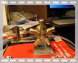
I am looking for a real cool project for my students and I would like to do your radial engine (AKA Brian's Radial Engine). What I really like about your engine is that there are no really small fragile parts and the engine parts would be easy to machine on our CNC machines. I would like to know if you would give me permission to use your radial engine as a project for my students.
If so, I would like to ask you a couple of questions.
CONROD HUB : After studying your drawings for quite a while, I would like to know if I have understood the mechanism properly. If the master Conrod is silver soldered to the Conrod Hub, that means that it never pivots (just thinking to myself !). If I understand correctly, the other Conrods are also fixed and do not pivot because they are fixed with Loctite. Is this correct? If this is correct, the only reason the engine can rotate is because the Cylinders pivot and the Conrod Hub probably rocks slightly back and forth for each revelation of the Crank ? Or is the the Loctite just to lock the small 1/8 inch rod that holds the end of the Conrod pin in place ?
If so . . . . I was thinking of doing a modification. If the above paragraph is correct, could I replace the Conrod Hub with a solid pentagon hub (with no groove) and drill and tap 5-40 at the correct spot on each face. The Conrods could then be simple threaded rods. Or am I missing something ?
When I first looked at the plans I was
sure that the other Conrods (other than the master one)
had to pivot in the Conrod Hub or they would break.
CYLINDER : I always buy Machinist's Workshop and Home Shop Machinist (that's how I found your engine !). So, after reading your explanation on page 26 of the Jan/Feb issue of Home Shop Machinist, I had a question regarding the path of the airflow in the engine. By the way, I took the liberty of changing the Air Inlet to an NPT pneumatic fitting (so my students can practice tapping NPT). I can follow the airflow path, starting from the side of the Vertical Stand, up into the circular annulus, into the (5 arm) Main Support Frame (via its own circular annulus), up the length of the arm and out the hole on the face of the arm. After that I presume it is the rocking action of the Cylinder that permits the air to enter into the top of the cylinder, pushes the Piston down and when the cycle is finished, the cylinder rocks (pivots) the other way (as the piston rises in the cylinder), letting the air exit by the other hole that goes completely through the arm. Is this correct ?
NOTE : I am using MasterCAMx7 to do all my drawings (production drawings, solids, etc) and to generate the G-codes to machine the parts. If you give me permission to do this project, I will keep you posted on my progress. I am attaching a screen grab of my progress so far.
Other modifications :
I will also be adding a small SHCS, screwed into the back of the flywheel so the student can rotate the engine manually and thus show off the interesting movement of the mechanism.


![20130422_185710[1].jpg 20130422_185710[1].jpg](https://cdn.imagearchive.com/homemodelenginemachinist/data/attach/24/24608-20130422-185710-1-.jpg)
![20130930_222917[1].jpg 20130930_222917[1].jpg](https://cdn.imagearchive.com/homemodelenginemachinist/data/attach/24/24609-20130930-222917-1-.jpg)
![Challenger_-_Ready_to_go[1].jpg Challenger_-_Ready_to_go[1].jpg](https://cdn.imagearchive.com/homemodelenginemachinist/data/attach/24/24610-Challenger---Ready-to-go-1-.jpg)