[SIZE=+2]BAYONET BACKPLATE FOR MY NEW CHUCK[/SIZE]
I have long felt the need for a chuck with 4 independently movable jaws and, needing it to make my QCTP, I finally ordered a 125mm Sharp from Chronos, UK. Four days later it had arrived in Rome. In the meantime I had purchased a 21mm slice from a 130mm bar of C40 steel from which to build a backplate to fix it to the spindle of my Prazimat lathe.
The Bayonet Spindle Interface
The following two photos show the bayonet type of spindle interface of my lathe.
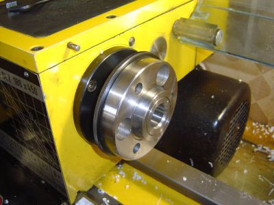
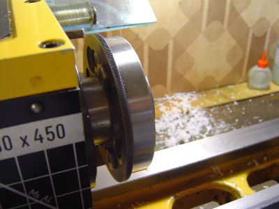
This interface conforms to the now obsolete DIN 550217 standard. With respect to the normal threaded interface, two advantages are claimed for the bayonet interface: a) it is equally safe and reliable for trasmission of rotational force in both directions and b) mounting and dismounting chucks and faceplates or whatever is quick and easy. A disadvantage is that you have to make your own backplates and these are rather complex.
The protruding conical section on the spindle plate serves to position the axis of the backplate exactly on the axis of the spindle every time the backplate is mounted. The three special "bolts and nuts" fix and hold the backplate in position against the splindle interface plate. In the second photo you can see the black steel bayonet plate behind the spindle interface plate. This bayonet plate has three keyhole shaped slots and can be rotated roughly 15 degrees about the spindle axis. In the open position the three nuts on the backplate pass through the large part of the keyholes on the bayonet plate; in the closed position the nuts can be tightened up (17mm spanner) against the bayonet plate to lock the backplate in position on the spindle.
Design Drawing and Build Plan
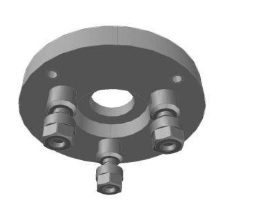
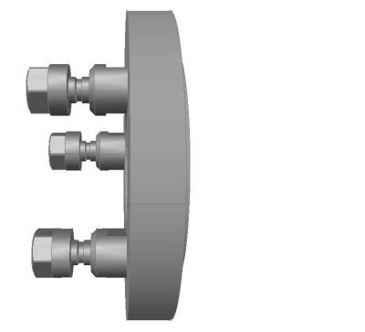
With the chuck on my desk I was in a position to make the detailed design and to plan the build sequence. The interface between the backplate and the chuck is simple enough. Correct positioning is ensured by a 95mm diameter protrusion 4mm wide on the bacplate. Four 8mm screws equispaced on a 108mm diameter fix and hold the chuck onto the backplate.
The following two images show two views from the 3D model of the backplate.
It seemed clear that I should first machine the interface to the lathe spindle so that then the interface to the chuck could be machined with the backplate mounted in it's regular position on the spindle. I saw two problems.
Here are a few photos taken during work in progress.
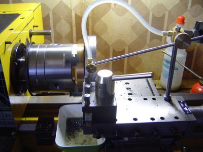
Machining the outer border ro ite final diameter of 127mm. Held in the 100m 3-jaw chuck you can see the bronze backplate to which the 130mm steel slice is bolted.
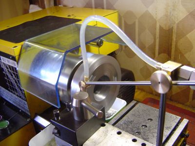
Machining the Spindle Interface. The bore has been rough machined and here the face is being faced off before completing the conical part of the bore.
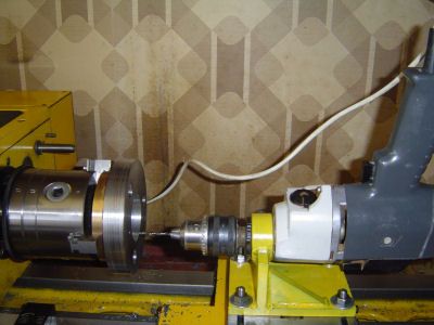
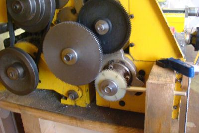
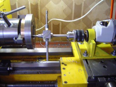
Drilling (8.5mm) and tapping (M10) the three holes for the bayonet bolts. The electric hand drill is held in a custom made mount fixed to the lathe's cross slide. For each of the three holes the rotational angle of the spindle is set by using the lathe's gear train for indexing as shown the second photo. The third photo shows the setup for manual tapping using my homemade tap guide. The electric drill's chuck is closed lightly on the shank of the guide to keep it on axis without impeding it's rotation. The tapping in C40 steel went off rather better than I had expected, alternating the 1 and 2 taps and using abundant lube juice without ever having to force very hard. For sizes up to M10, I actually prefer this rather small tap holder because it helps avoiding the application of a lot of force which shouldn't be necessary. In fact, when the time came to tap the four M8 holes for the bolts which fix the chuck to the backplate, I realized that too much force was required and so went out to buy a new set of taps.
The result
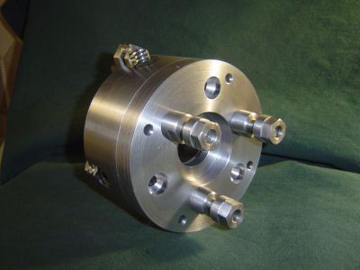
The photo below shows the finished backplate mounted on the new chuck. I "borrowed" the three bolts and nuts from another interface so sometime I will have to make new ones.
Now I can resume work on the Base of my Quick Change Tool Post.
I have long felt the need for a chuck with 4 independently movable jaws and, needing it to make my QCTP, I finally ordered a 125mm Sharp from Chronos, UK. Four days later it had arrived in Rome. In the meantime I had purchased a 21mm slice from a 130mm bar of C40 steel from which to build a backplate to fix it to the spindle of my Prazimat lathe.
The Bayonet Spindle Interface
The following two photos show the bayonet type of spindle interface of my lathe.


This interface conforms to the now obsolete DIN 550217 standard. With respect to the normal threaded interface, two advantages are claimed for the bayonet interface: a) it is equally safe and reliable for trasmission of rotational force in both directions and b) mounting and dismounting chucks and faceplates or whatever is quick and easy. A disadvantage is that you have to make your own backplates and these are rather complex.
The protruding conical section on the spindle plate serves to position the axis of the backplate exactly on the axis of the spindle every time the backplate is mounted. The three special "bolts and nuts" fix and hold the backplate in position against the splindle interface plate. In the second photo you can see the black steel bayonet plate behind the spindle interface plate. This bayonet plate has three keyhole shaped slots and can be rotated roughly 15 degrees about the spindle axis. In the open position the three nuts on the backplate pass through the large part of the keyholes on the bayonet plate; in the closed position the nuts can be tightened up (17mm spanner) against the bayonet plate to lock the backplate in position on the spindle.
Design Drawing and Build Plan
With the chuck on my desk I was in a position to make the detailed design and to plan the build sequence. The interface between the backplate and the chuck is simple enough. Correct positioning is ensured by a 95mm diameter protrusion 4mm wide on the bacplate. Four 8mm screws equispaced on a 108mm diameter fix and hold the chuck onto the backplate.
The following two images show two views from the 3D model of the backplate.


It seemed clear that I should first machine the interface to the lathe spindle so that then the interface to the chuck could be machined with the backplate mounted in it's regular position on the spindle. I saw two problems.
- - How should I the hold the raw slice to machine the interface to the spindle? My 100mm self-centering 3-jaw chuck was too small. In the end I decided to bolt the raw slice onto a existing 100mm bronze backplate and then hold that backplate in the 3-jaw chuck. The heads of the three temporary bolts would clearly have to be sunk below the surface to be maachined. The finished backplate would therefore forever carry these scars of its birth pangs!
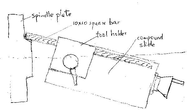
- - How could I set the compound slide to the correct angle for the conical section? Having failed to find any trace of the standard on the DIN internet site, I do not know the nominal value of this angle. After attempting to measure the angle on the spindle cone, I decided to try to set the angle of the cross slide directly from the angle on the cone. To do this I mounted a 200mm length of 10mm square bar (actually a new bar of ground HSS tool steel) in the tool holder parallel to the axis of the compound slide and then adjusted the angle and Y position (cross slide) of the compound slide so that the protruding end of the square bar lay precisely along the profile of the spindle cone. Unfortunately I was so concentrated on this process that I forgot to take a picture. However even a terrible drawing is better than bare words, so here is a very rough hand sketch.
Here are a few photos taken during work in progress.

Machining the outer border ro ite final diameter of 127mm. Held in the 100m 3-jaw chuck you can see the bronze backplate to which the 130mm steel slice is bolted.

Machining the Spindle Interface. The bore has been rough machined and here the face is being faced off before completing the conical part of the bore.


Drilling (8.5mm) and tapping (M10) the three holes for the bayonet bolts. The electric hand drill is held in a custom made mount fixed to the lathe's cross slide. For each of the three holes the rotational angle of the spindle is set by using the lathe's gear train for indexing as shown the second photo. The third photo shows the setup for manual tapping using my homemade tap guide. The electric drill's chuck is closed lightly on the shank of the guide to keep it on axis without impeding it's rotation. The tapping in C40 steel went off rather better than I had expected, alternating the 1 and 2 taps and using abundant lube juice without ever having to force very hard. For sizes up to M10, I actually prefer this rather small tap holder because it helps avoiding the application of a lot of force which shouldn't be necessary. In fact, when the time came to tap the four M8 holes for the bolts which fix the chuck to the backplate, I realized that too much force was required and so went out to buy a new set of taps.
The result
The photo below shows the finished backplate mounted on the new chuck. I "borrowed" the three bolts and nuts from another interface so sometime I will have to make new ones.

Now I can resume work on the Base of my Quick Change Tool Post.


