Another X2 Mod thread

Home Model Engine Machinist Forum

Help Support Home Model Engine Machinist Forum:

This site may earn a commission from merchant affiliate links, including eBay, Amazon, and others.

rythmnbls

Well-Known Member
Joined
Jan 14, 2012
Messages
115
Reaction score
31
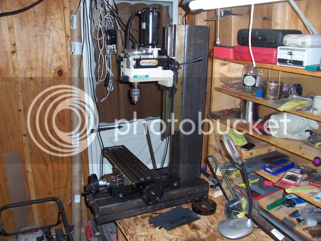
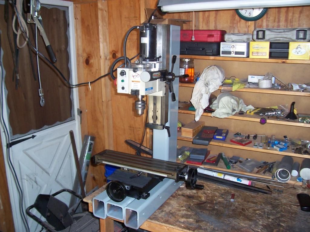
Inspired by a couple of threads by forum member Bill S, I decided to give my X2 mill some extra rigidity and Z travel. Here are a few photos of progress.
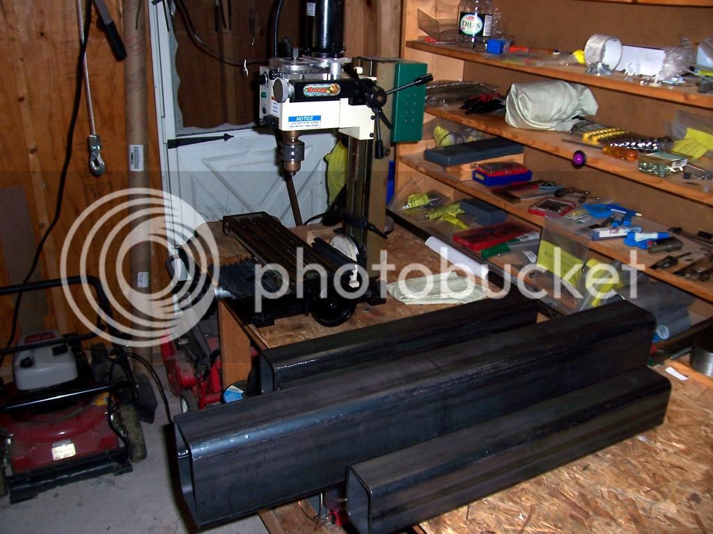


Photo of the starting materials and the unsuspecting mill in the background. Shown are the base materials - 3"x4" square tubes with a .375" wall thickness and a 4"x6" square tube with a .375" wall thickness destined for the column support.
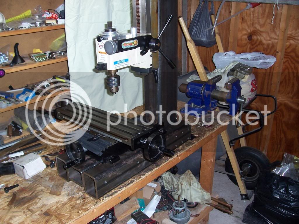
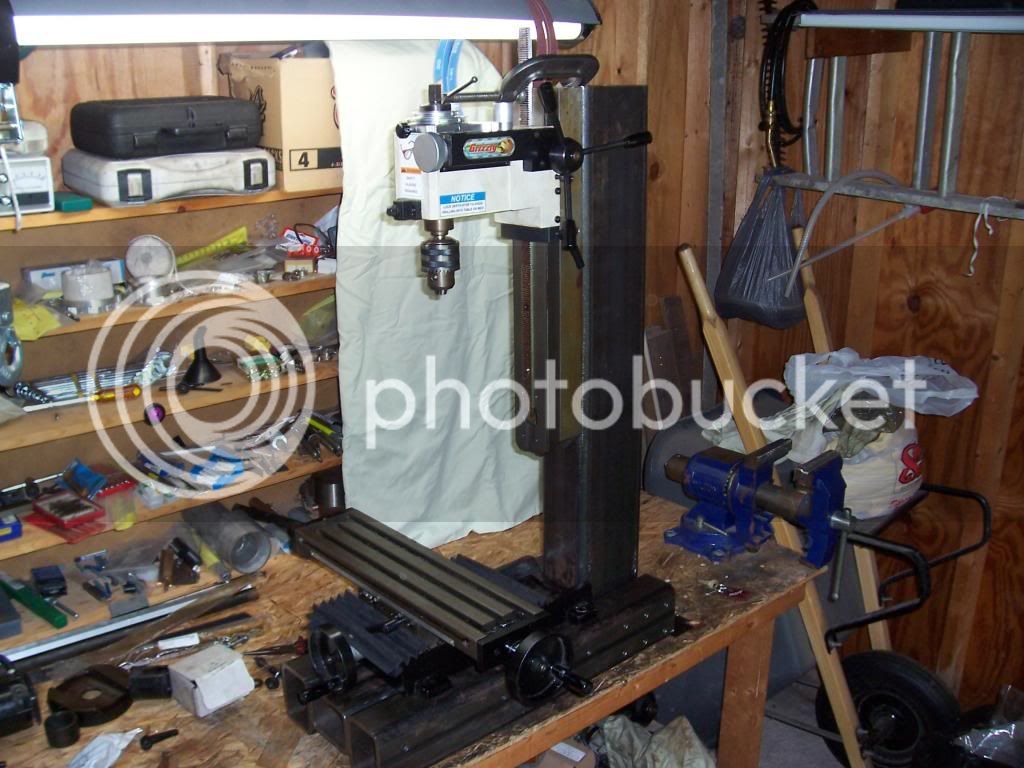


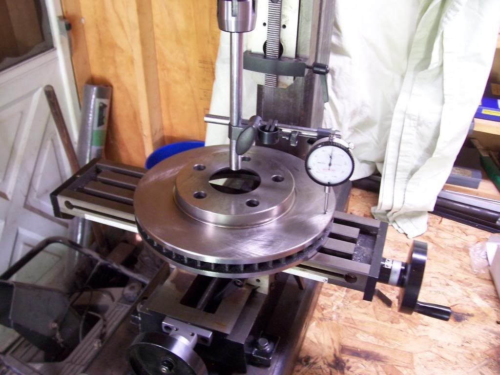
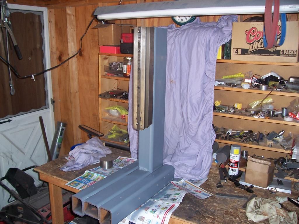
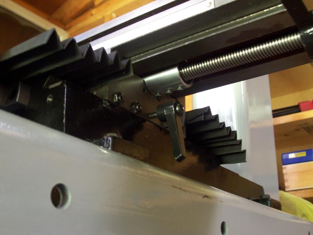
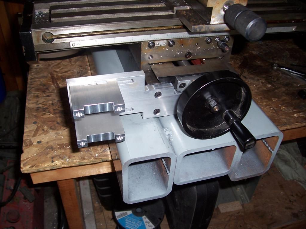
Photos of the assembled base showing the extent of the Z travel. There should be plenty of room for the rotary table with a 4 or 3 jaw chuck and work piece which is a machining operation I could never do previously.

I still have to mount the extended Z rack, and bolt the XY table to the base, tram all axes and throw some paint on it.

Some links to the original threads by Bill S
http://www.homemodelenginemachinist.com/f28/small-x2-mod-7479/
http://www.homemodelenginemachinist.com/f28/x2-upgrade-update-7779/
http://www.homemodelenginemachinist.com/f28/x2-mods-finished-7846/

Thanks for reading.

Steve.
 
Nice Steve! 😜😜😜


How much effort was required to get the Z square to the rest of the machine?
 
Work is progressing on the mill. The new extended Z rack has been drilled, countersunk and mounted. Work has started on tramming the Z axis to the table.


Photo of the mill with the completed Z rack mounted.

To get the X axis in alignment a .020" shim was needed under left table feet. It is now within .001" which I'm happy with, Y tram is within .007" and will have to wait till I buy some appropriate shim stock to dial it in.


Photo of tramming the mill.

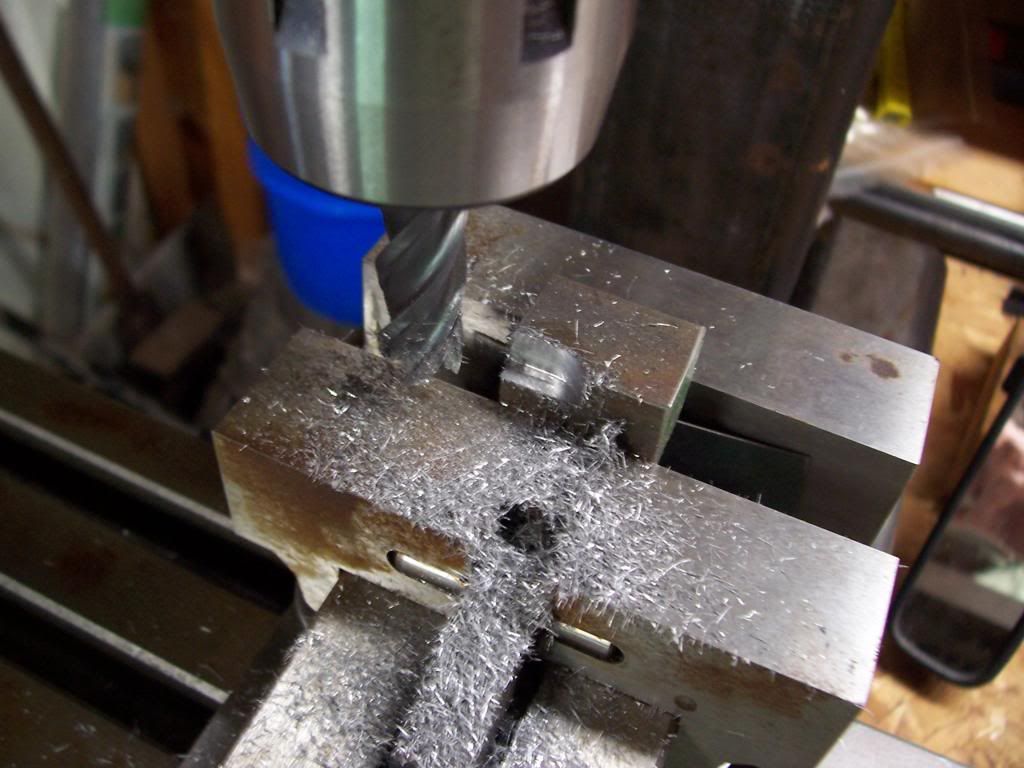
I couldn't resist taking a few test cuts, here's shot of a .250" doc with .150" infeed in some 4140 square stock using a .5" endmill, although there was some resonance noise, there was no chatter or thumping that would have normally been expected with a cut like this, I'm very happy with the result so far.


And a closer shot of the completed cut, finish is pretty good for a roughing cut.


I still need to build a counterweight for the head, and paint the bare steel parts. Considering how much of an improvement this has been, I'm thinking it might be worth hand scraping the ways and gibs as they are just rough milled at the moment. A decent vise wouldn't hurt either :)


Thanks for reading.

Steve.
 
Fill that tube with sand and it will be rock solid just drain out the sand before you try to move it LOL.
Tin
 
I couldn't resist taking a few test cuts, here's shot of a .250" doc with .150" infeed in some 4140 square stock using a .5" endmill, although there was some resonance noise, there was no chatter or thumping that would have normally been expected with a cut like this, I'm very happy with the result so far.


Thanks for reading.

Steve.
I wouldn't be able to resist either. You have a very interesting build here, effectively a new mill!!!

Tin mentioned filling the tubes with sand and frankly doing something along those lines might be icing on the cake so to speak. I'd seriously consider epoxy granite infill. Of course you may need to spend three weeks at the Gym before you attempt to move it each time.
 
Good idea. Interesting to have more Z travel on the mini mill.....many times I wished had a couple more inches.
 
Thanks for all the positive comments, much appreciated.

Fill that tube with sand and it will be rock solid just drain out the sand before you try to move it LOL.

Tin mentioned filling the tubes with sand and frankly doing something along those lines might be icing on the cake so to speak. I'd seriously consider epoxy granite infill. Of course you may need to spend three weeks at the Gym before you attempt to move it each time.
Very interesting comments, as I mentioned there was some resonance noise during the test cut which was probably amplified by the steel tubing, much like a bell. I do like the idea of removable damping as there are assembly bolts that would be inaccessible if epoxy was used. Food for thought, thanks again for those ideas.

Regards,

Steve.
 
This thread is a bit overdue for an update
smiley.gif


First up was a thorough cleaning, a few welds to lock everything in place and a bit of paint to make it look nice and to cover my ugly welds up.


Re-assembled..


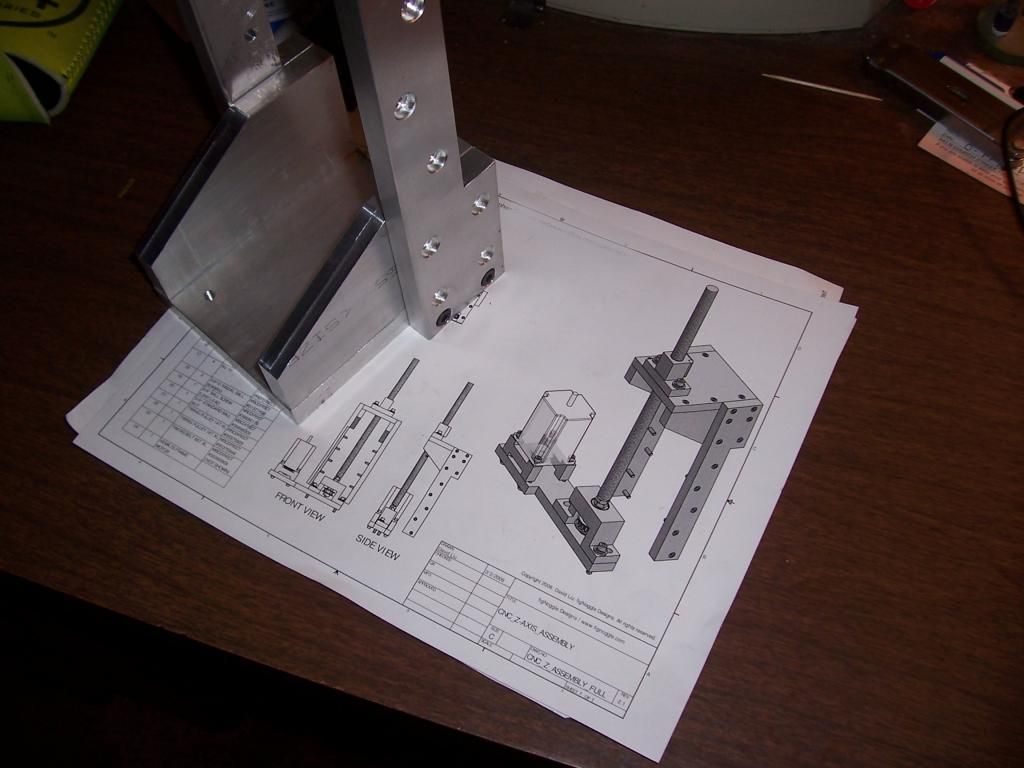
Then I decided I wanted to convert it to CNC, so I purchased the figNoggle plans ( www.fignoggle.com ).

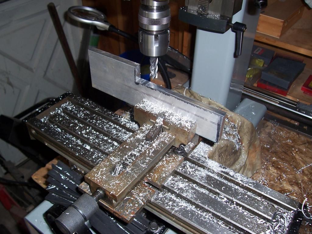
A progress shot of making the Y-axis mounting bracket, I really do need to get a better vise.


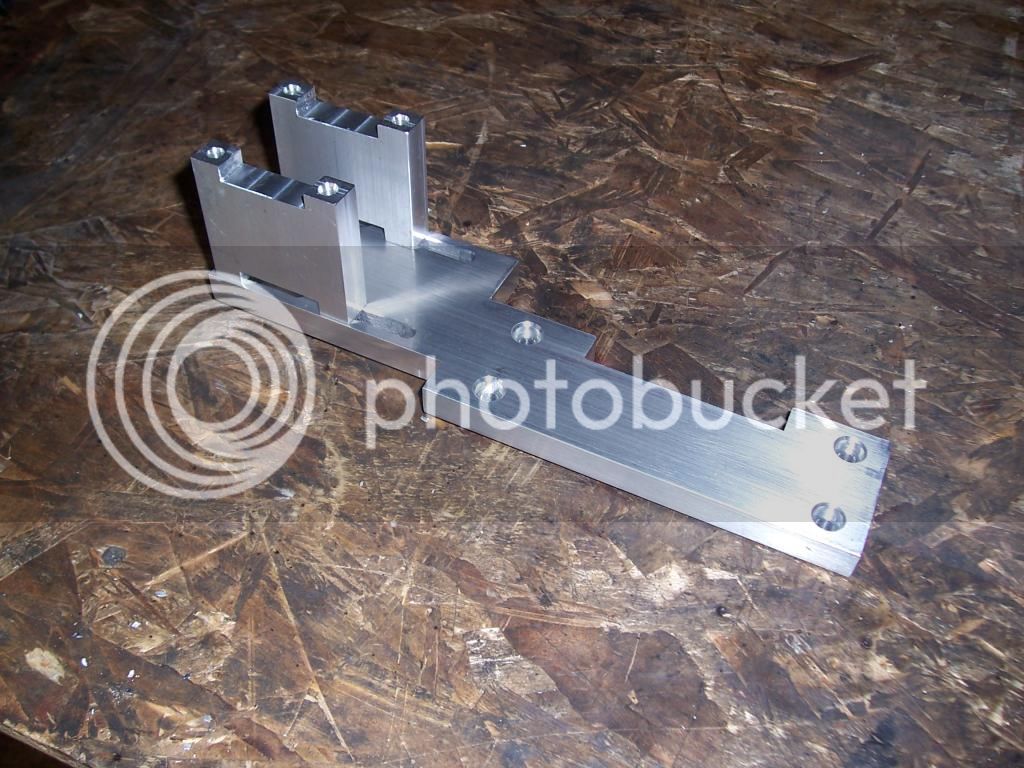
A pic of the completed bracket.


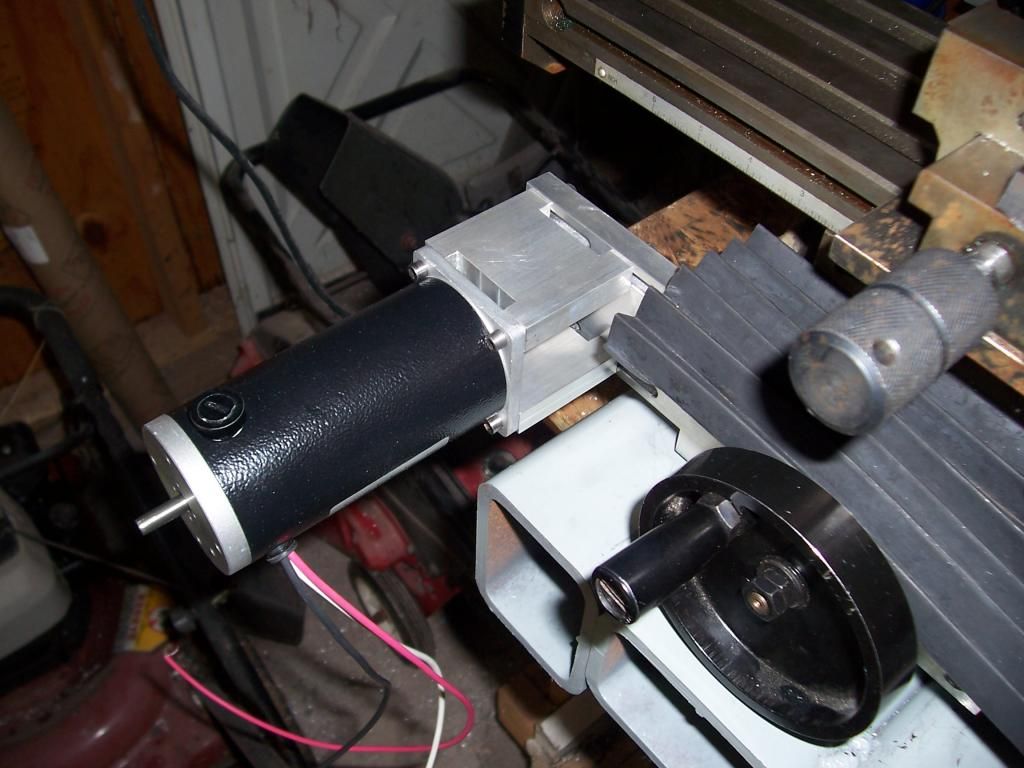
A couple of pics showing it mounted on the mill.


Next was zero backlash Y-axis leadscrew. I decided to try an acetal leadscrew nut based on this thread at HSM http://bbs.homeshopmachinist.net/threads/43645-Making-Acetal-leadscrew-nuts-the-easy-way as they should be a lot cheaper than ball screws. So I bought some precision acme 5/8-10 rod and some Delrin and went at it :)

Pic of making the nut..


Turning the leadscrew..


Milling a keyway...


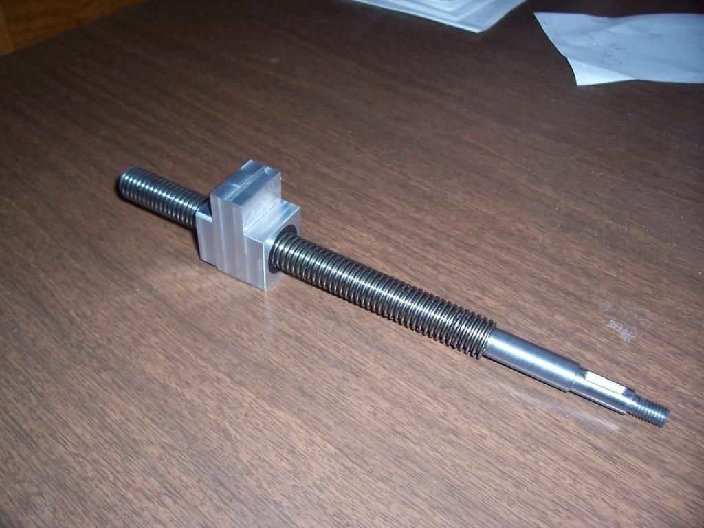
Completed leadscrew and nut.


Fitted to the mill.


I'm really pleased on how this turned out, the Y axis is really smooth and has no backlash at all.

The plan now is start on the X axis this weekend make some chips and hopefully not to much scrap. :D

Happy memorial weekend to all.

Regards.

Steve
 
Very nice work. I am planning to brace up the column on my mill but you really take the cake with this mod.

Shawn
 
Thanks Shawn.

The X axis screw is just about finished, it just needs a key slot milled.

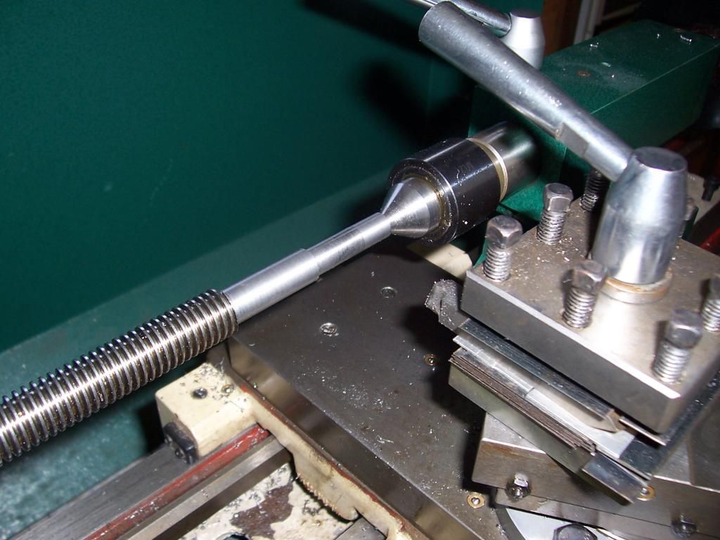
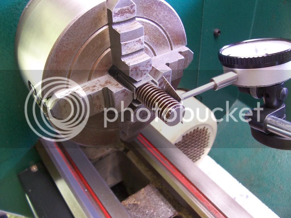
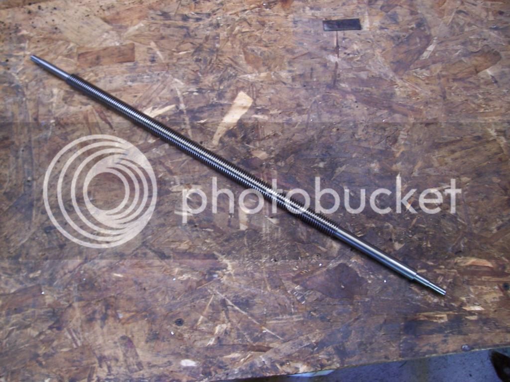
The leadscrew is about 22.5 inches long and was a bit tricky getting the center holes drilled accurately. I had to make a bushing to fit the outboard end of the lathe spindle to stop it moving around during turning. I also had to use a bit of shim stock between the screw and the dial gauge to get it centered, in the end it all worked out pretty well.
Here are a few pics of the setup and progress.


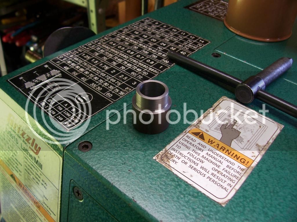
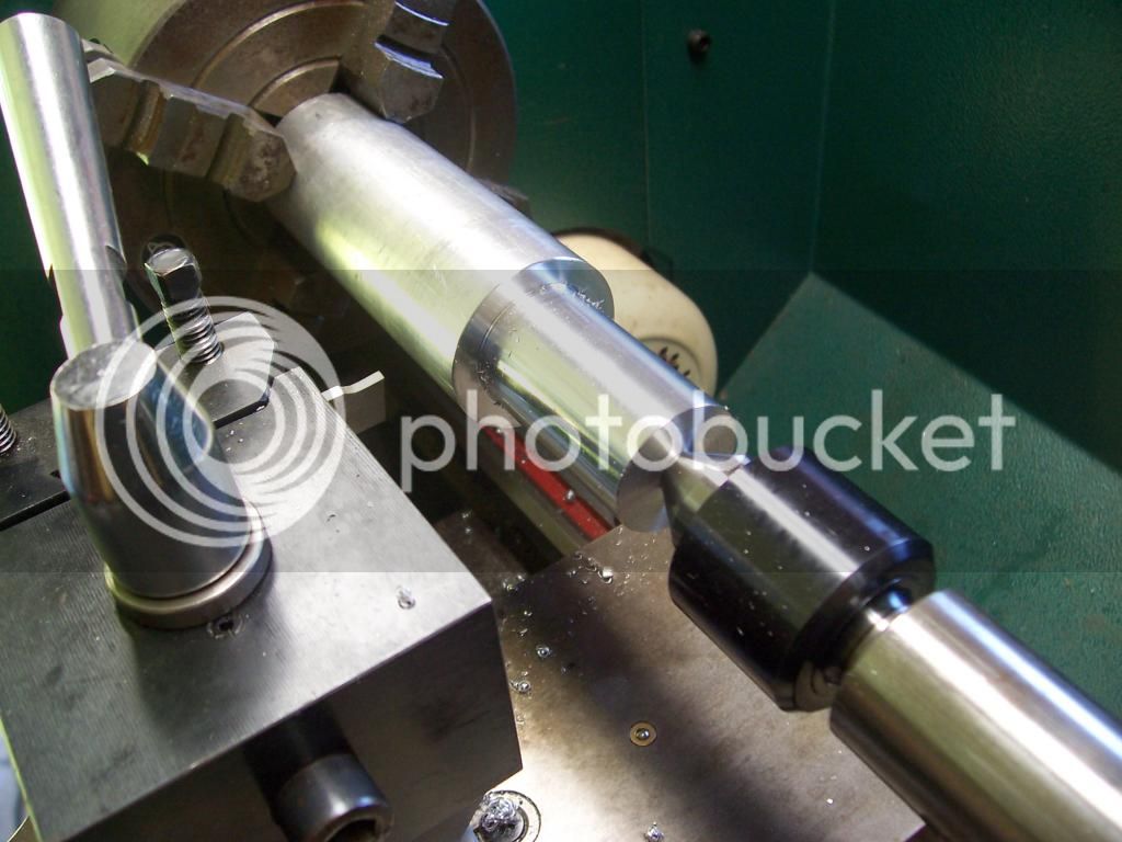
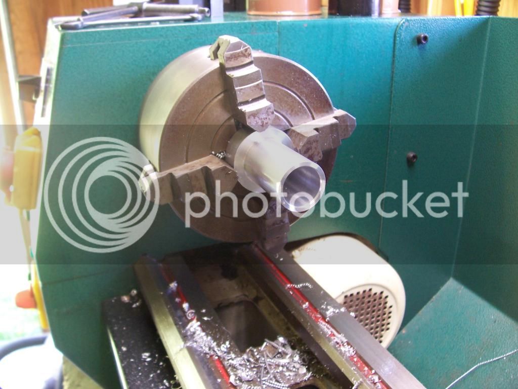
Pic of the bushing, id is .625, od .800


Pic of the bushing installed.


Using the shim to dial in the leadscrew.


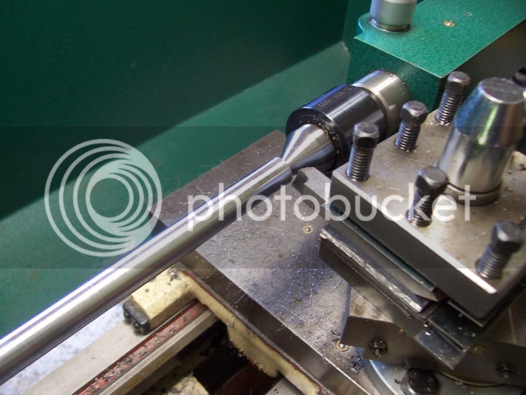
Pic of finish turning the the servo drive end of the shaft, the tool is a shear tool which gives a really nice finish on most steels. More info on the tool here. http://www.gadgetbuilder.com/VerticalShearBit.html


Finished drive end.


Single pointing an 8mm x 1.25 thread for the hand wheel retaining nut.


Turning done.


Thanks for reading.

Steve.
 
Continuing on..

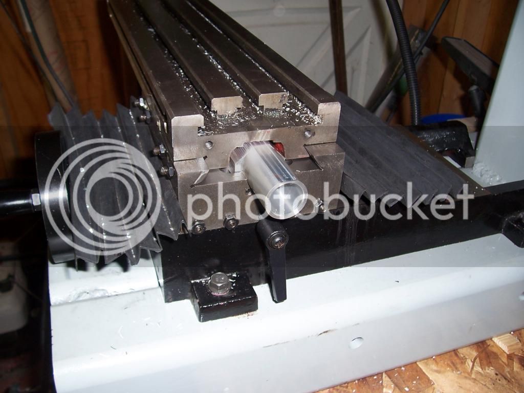
Pic of making the X axis nut holder, this will have an acetal liner pressed into it when its completed.


Here I have just finished boring the hole for the liner. The flange will be milled to clear underside of the table.


Photo of the nut holder mounted in the saddle, showing the clearance to the table.


Photo of the completed nut, the screws are there for insurance as the liner was turned .003" oversize for a good tight press fit in the holder.


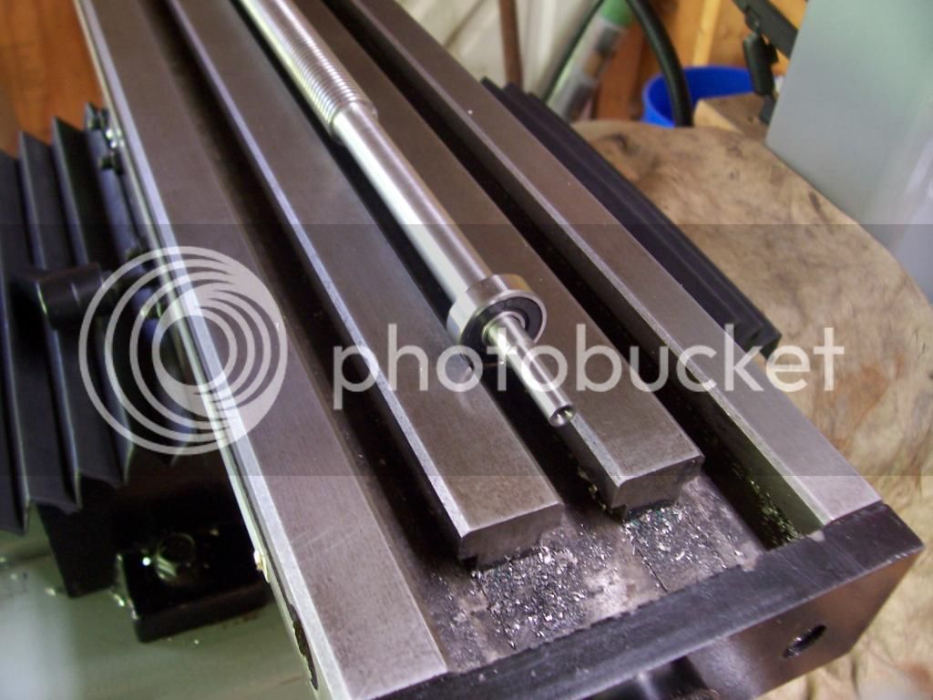
Photo of the completed leadscrew and nut.


...and mounted in the saddle.


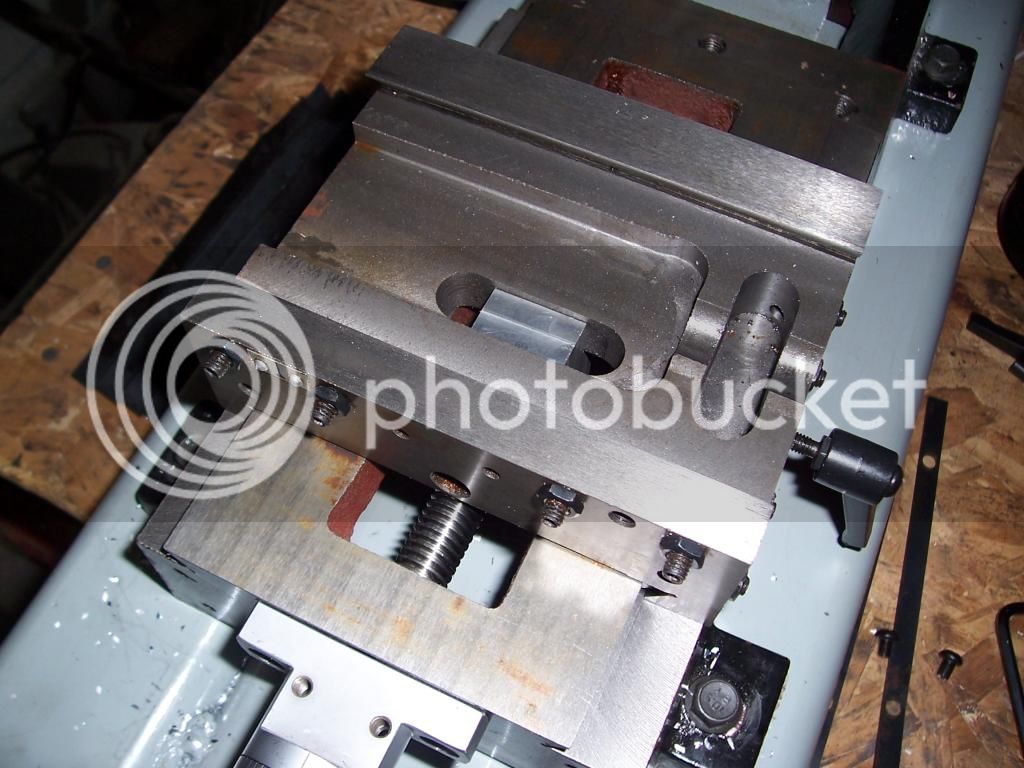
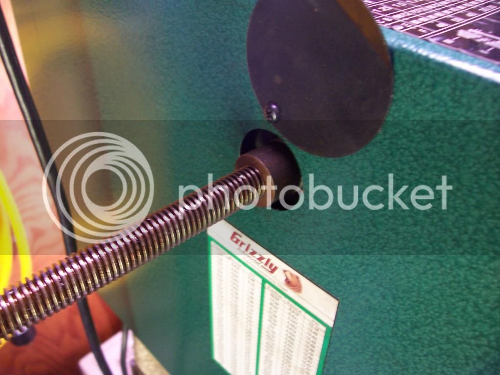
This is the end plate that held the far end of the old lead screw, the old leadscrew has a bronze bushing attached which rotated in the bore of the plate. The conversion plans I bought do away with this bushing and use the servo motor to locate the leadscrew. I decided that I did not like this idea and will fit a 608 bearing in this plate to locate the leadscrew.


Photo of the plate with bearing pressed in.


Photo of the underside of the table after fitting the leadscrew and nut.


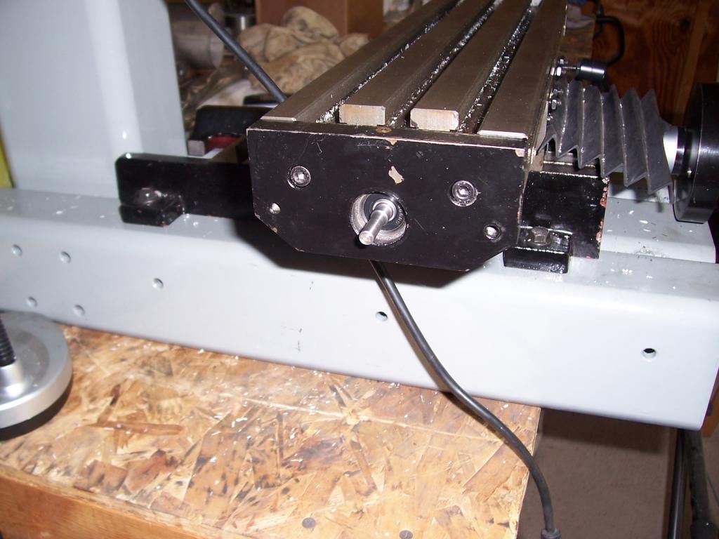
Photo of the far end of the table where the servo will mount.


Thats all the updates I have at the moment, I have made some test cuts with the new leadscrews fitted and I'm very pleased with the results, they are very smooth and the zero backlash is a real plus.

Thanks for reading.

Steve.
 
A few more parts have been crossed off the check list, most of which are for the Z axis.

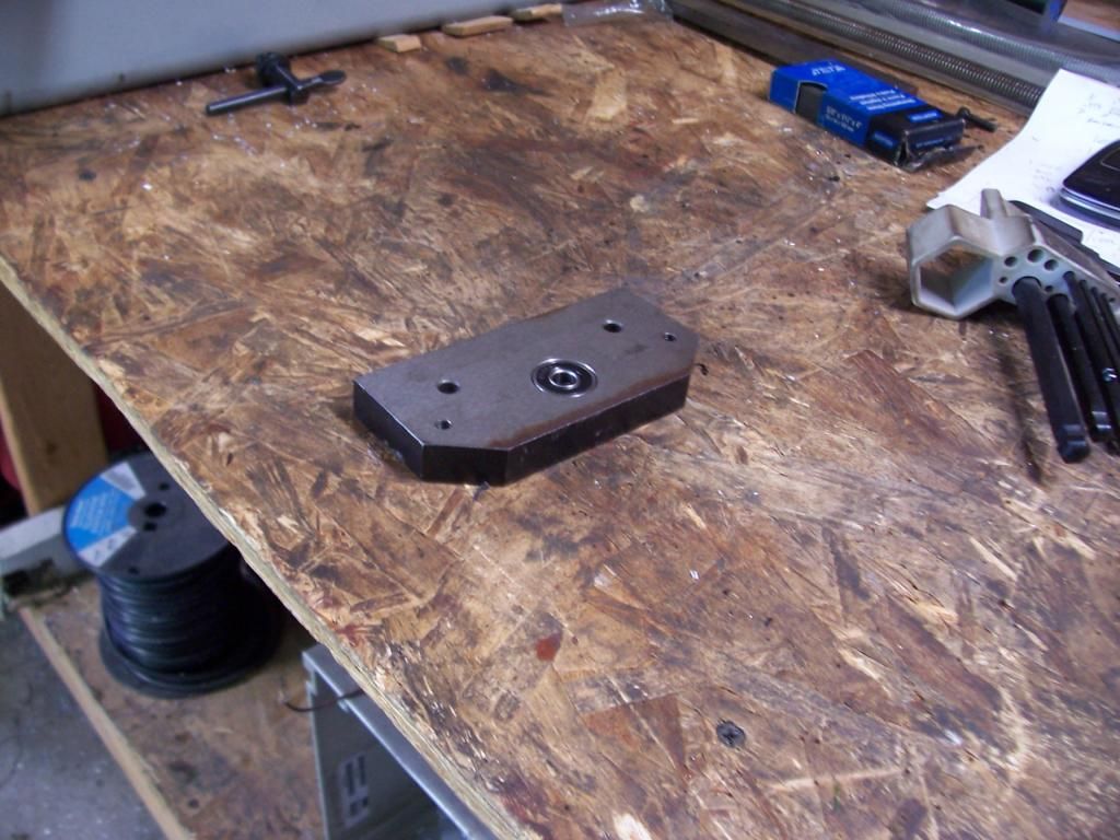
Here's a pic of the general layout. The leadscrew nut is mounted on the top bracket and the leadscrew is attached to the mill head by a bearing block and motor plate.


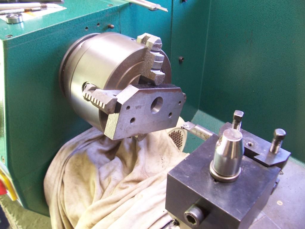
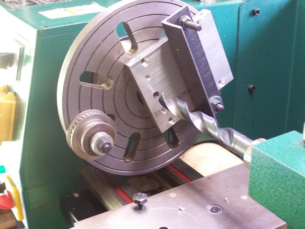
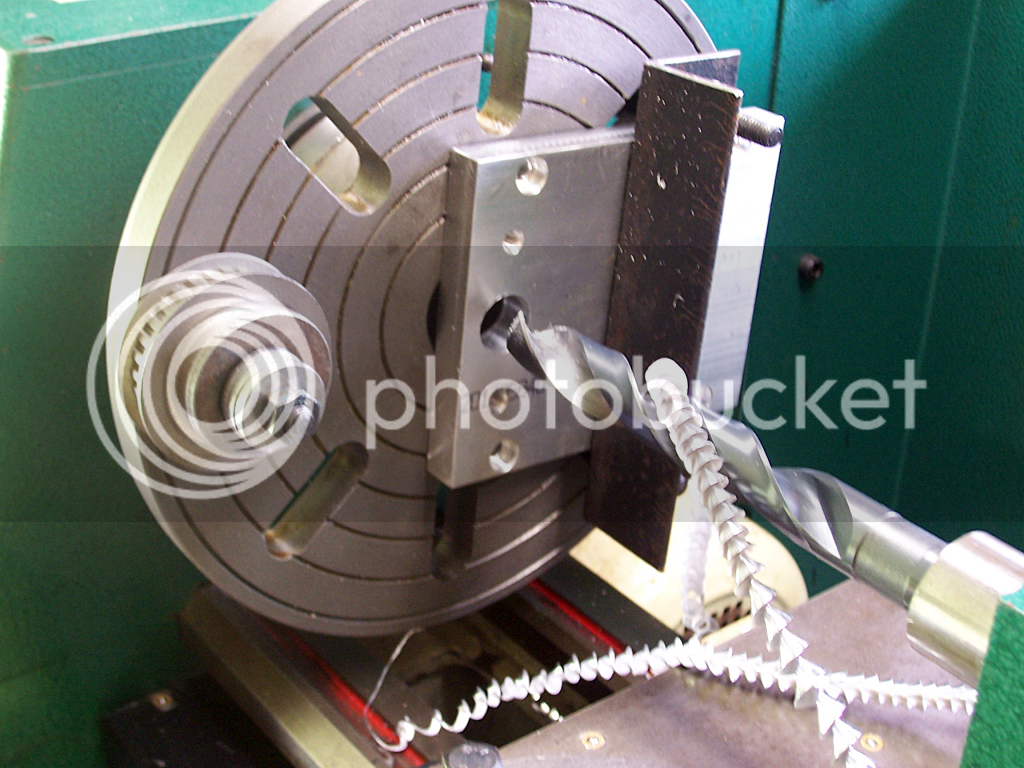
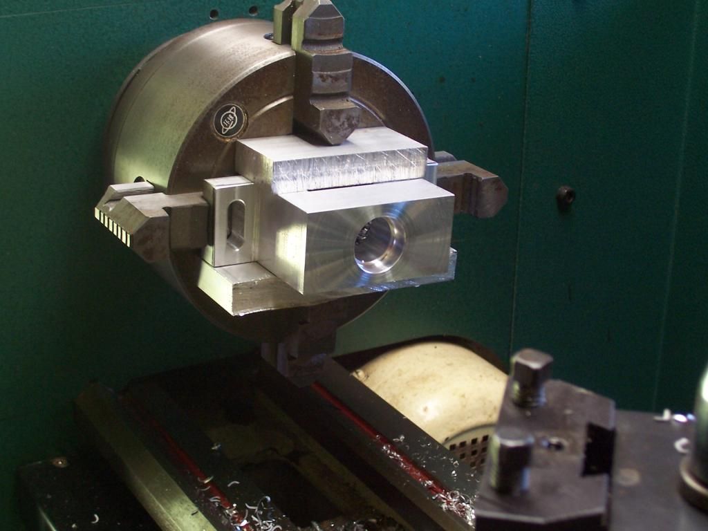
A few shots of drilling the leadscrew clearance hole in the top plate. Since I don't have a boring bar and the drill's morse taper doesn't match that of the quill in the mill, I had to use the faceplate in the lathe. This is the first time I've used that faceplate so I was quite pleased with the result.


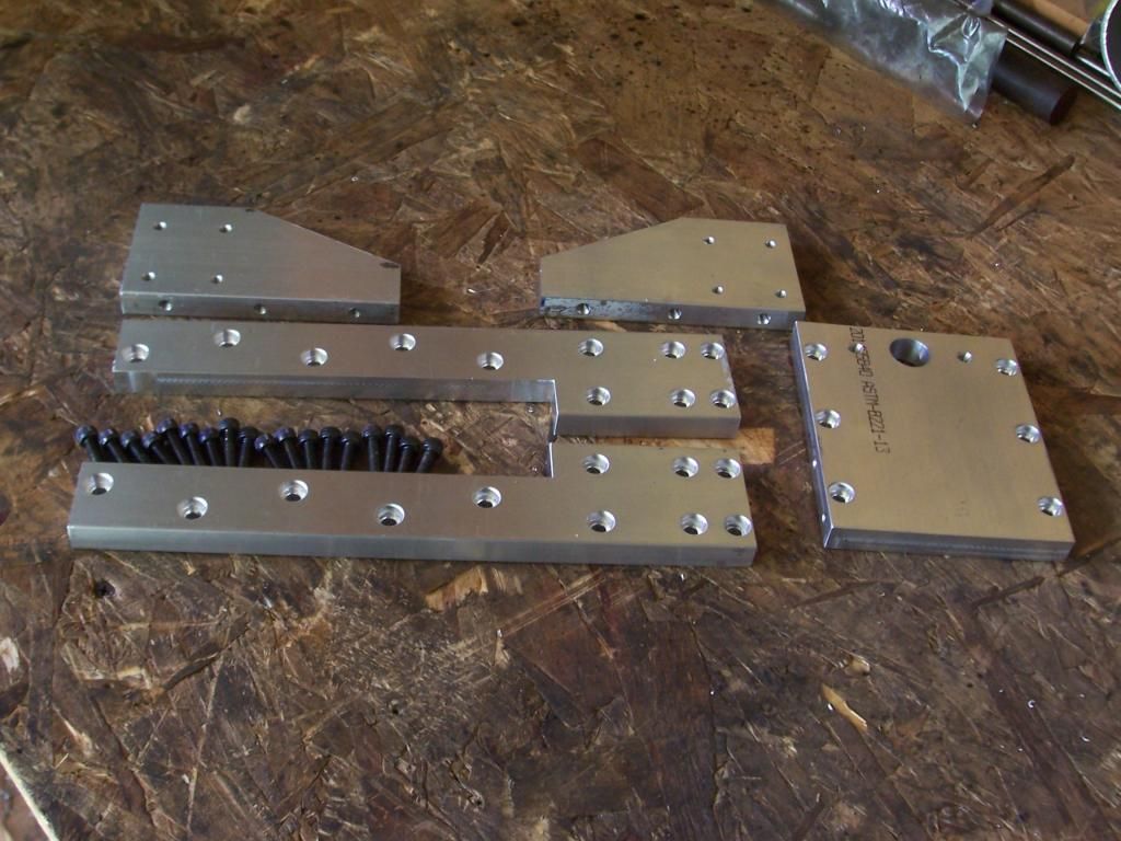
A shot of the upper z-axis parts, a lot of drilling tapping and counter-boring.


Here's a shot of bracket sitting on the mill, I intend to mount the assembly further forward than is called for in the plans as I want to add a counter weight pulley system which will attach to the motor base plate just behind the leadscrew. Fortunately, the belt drive conversion moves the motor forward otherwise there'd be no room.


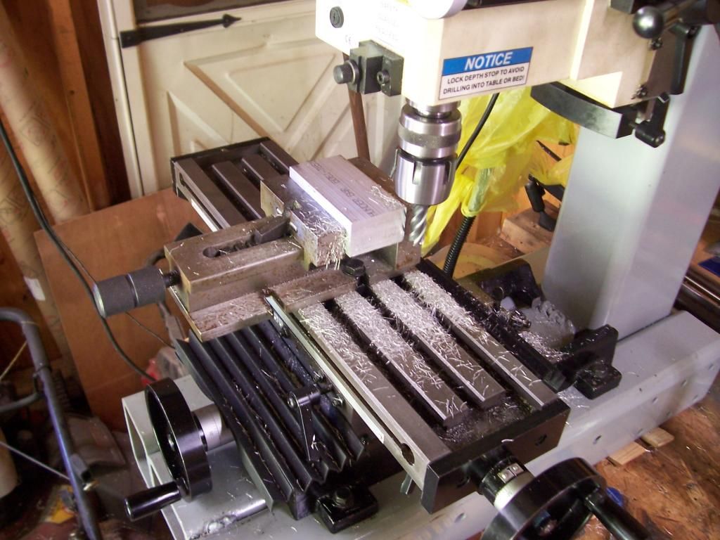
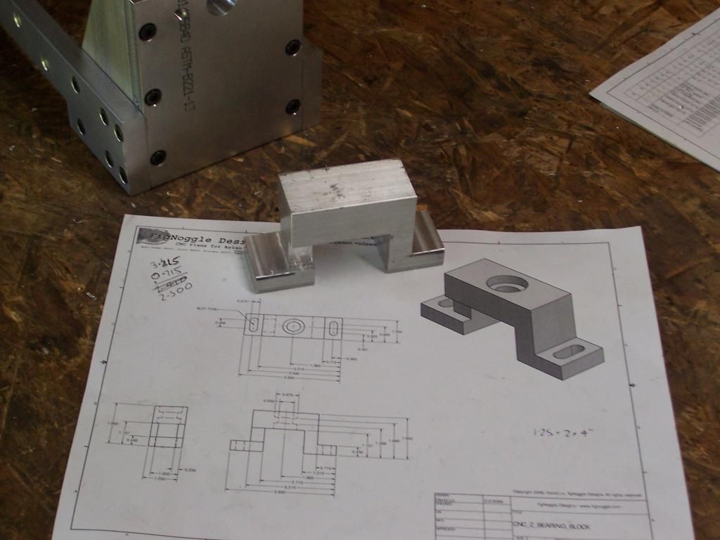
A start has been made on the lower bearing block. One advantage of the extra rigidity of the new mill base is the ability to take a full depth side milling pass like this. Material thickness is 1.25". The mill will happily take .040" at this depth.


Here's the bearing block with most of the milling ops completed.


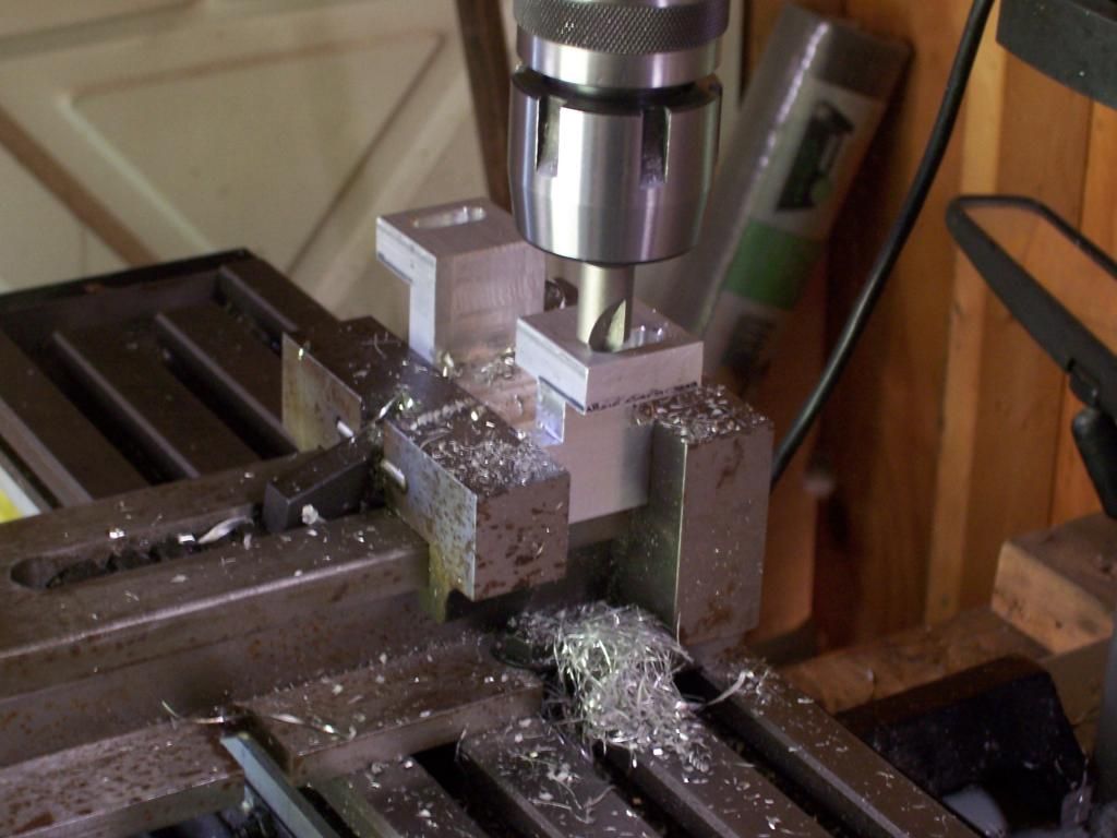
Countersinking / deburring the mounting slots


Counter-boring the holes for the top bearing.


That's all I have for now, thanks for reading.

Steve.
 
Last edited:
Awesome !!

I joined this forum just for the machining tips. I'm no machinist, but having always wanted a mini-mill, I finally bought an x2. I love seeing all the mods. While most of it is still over my head, as I learn through smaller projects, I can see the how's and why's of most of the mods. Please Please Please keep the ideas coming. And I'm really liking the individual parts and WIP pics. Really helps us amateurs and wannabees see how it all comes together.
Thank you for the feedback Thm: It is very much appreciated.

BTW I'm no machinist either, I'm just a hobbyist and an amateur.

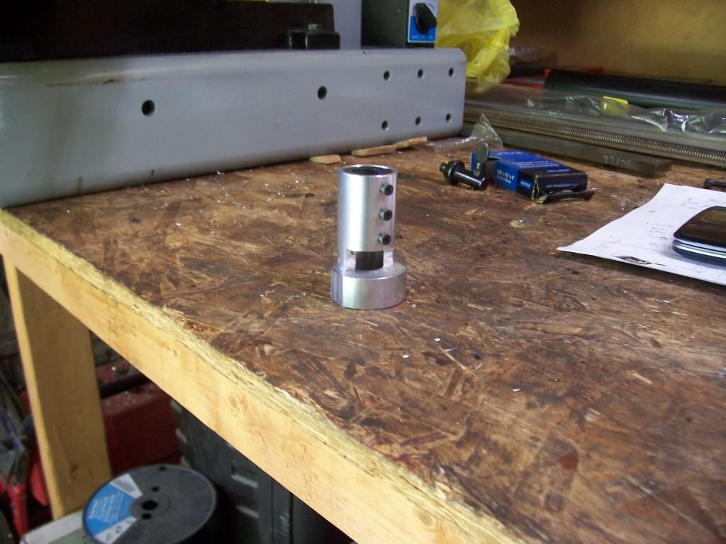
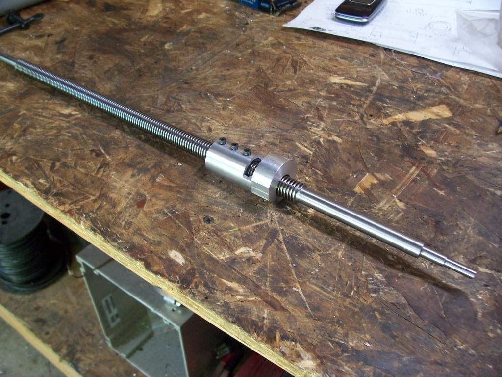
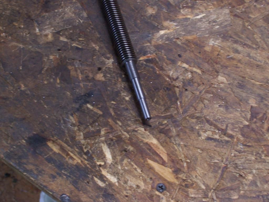
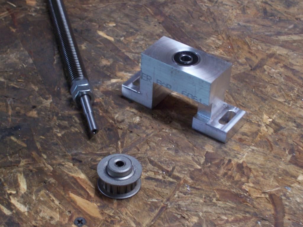
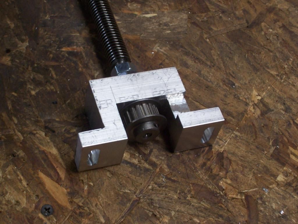
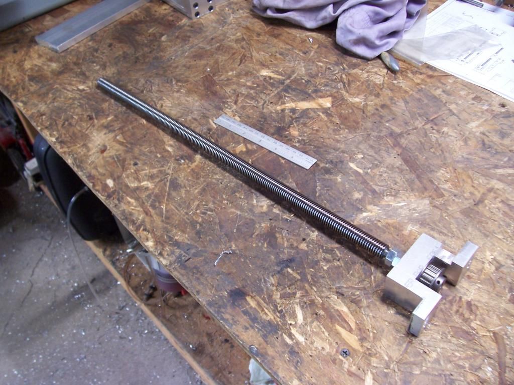
I did manage to get a bit more done on the Z axis parts. The leadscrew has been machined, just a basic turning job with a couple of shoulders machined on one end. The first shoulder was single point threaded to fit two 10mm x 1mm locknuts and the others were turned fit the bearings and the drive pulley. Here's a pic.


And a pic showing the bits before assembly....


...and assembled.


And finally a shot next to a 6" scale.


Next up is a counterweight system for the mill head, I don't want to fit the z-axis parts till it is done, I'm also planning on filling the tubular steel sections with an epoxy-granite mix of some sort.

Thanks for reading.

Steve.
 
A small update this week..

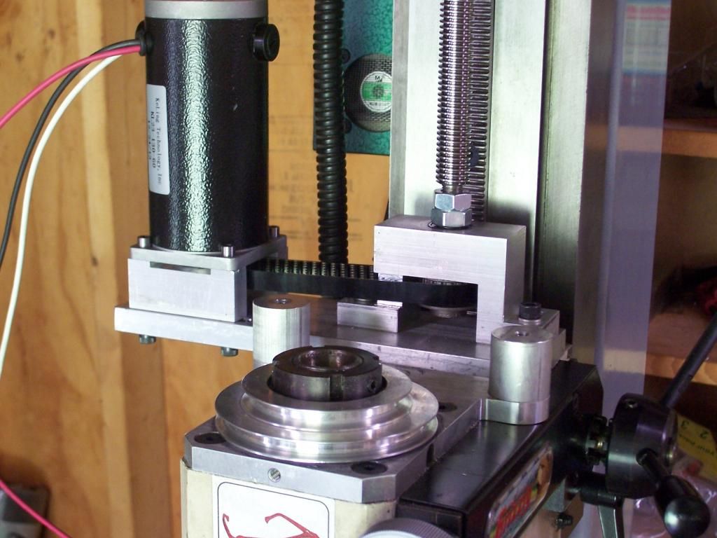
The counterweight system was put on the back burner when I realized I needed to get the Z axis bits mounted first to provide an attachment point for the counterweight. Here's the Z axis motor mount along with the bearing block which will also provide the attachment for the counter weight.


And a photo of it mounted on the mill.


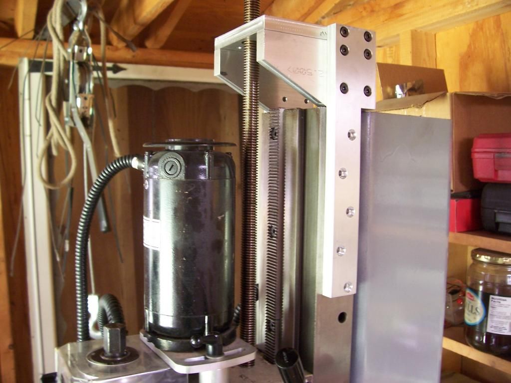
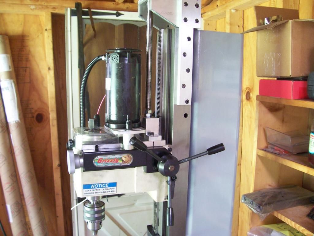
And finally a photo with the motor in position and a view of the upper leadscrew nut mount.


That's all I have for now, thanks for reading.

Steve.
 
Inspired by a couple of threads by forum member Bill S, I decided to give my X2 mill some extra rigidity and Z travel. Here are a few photos of progress.


Photo of the starting materials and the unsuspecting mill in the background. Shown are the base materials - 3"x4" square tubes with a .375" wall thickness and a 4"x6" square tube with a .375" wall thickness destined for the column support.


Photos of the assembled base showing the extent of the Z travel. There should be plenty of room for the rotary table with a 4 or 3 jaw chuck and work piece which is a machining operation I could never do previously.

I still have to mount the extended Z rack, and bolt the XY table to the base, tram all axes and throw some paint on it.

Some links to the original threads by Bill S
http://www.homemodelenginemachinist.com/f28/small-x2-mod-7479/
http://www.homemodelenginemachinist.com/f28/x2-upgrade-update-7779/
http://www.homemodelenginemachinist.com/f28/x2-mods-finished-7846/

Thanks for reading.

Steve.


I am just starting on doing a similar mod to mine with a steel frame what overall hight did you end up going for for the main post to maximise travel?
 
The main post is 36" x 4" x 6", the two outside base pieces are 4" x 3" x 24" and the inner base piece is 4" x 3" x 18", all pieces have a wall thickness of .350-.375"

Regards.

Steve.
 
Last edited:
The main post is 36" x 4" x 6", the two outside base pieces are 4" x 3" x 24" and the inner base piece is 4" x 3" x 18", all pieces have a wall thickness of .350-.375"

Regards.

Steve.

Cheers many thanks soon as i can sort a blade for my chop saw i will get to work.
 
Most of the counterweight parts have been completed, it consists of two rollers supported by 608 size ball bearings, a recycled crucible from my casting furnace and a length of stainless steel cable.

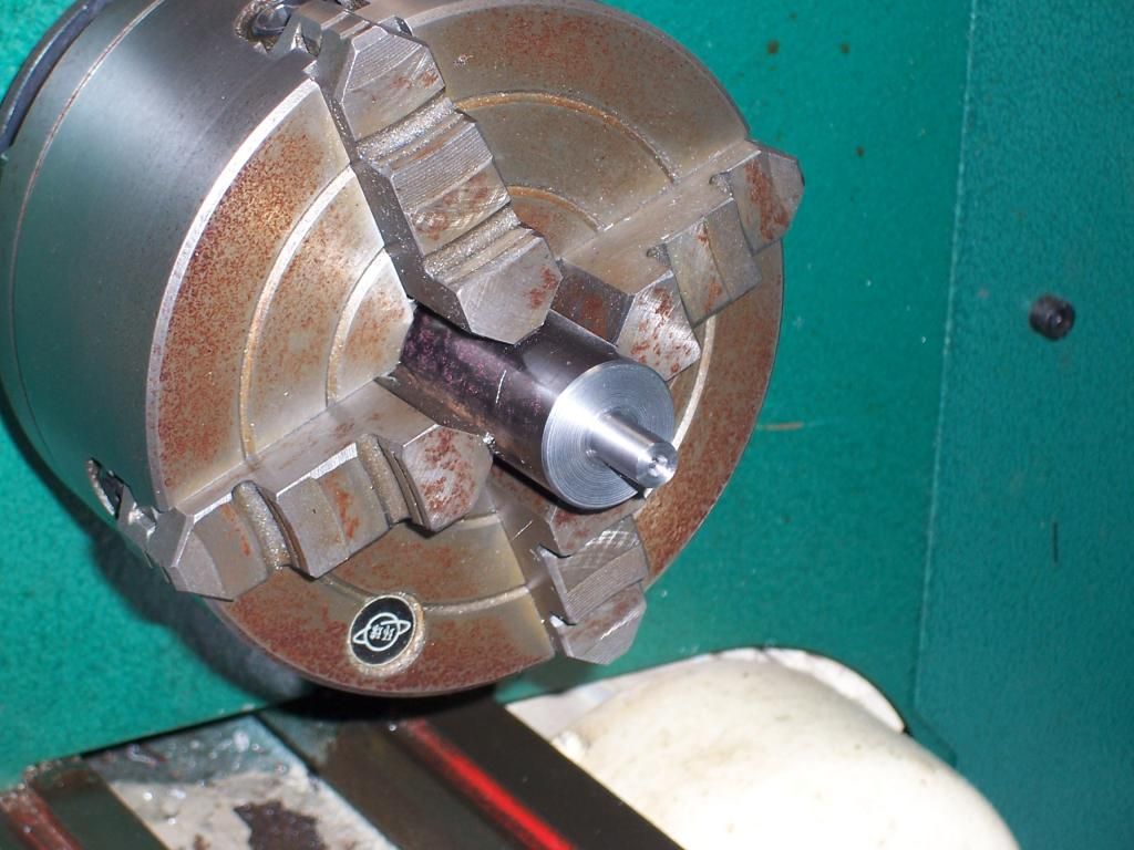
Here's a pic of turning one of the bearing journals for the front roller.


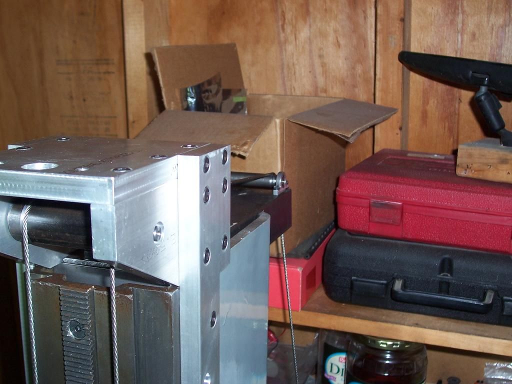
A pic showing the front and rear rollers with the cable in place.


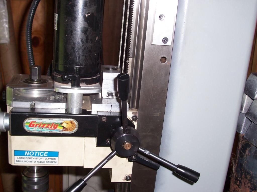
The cable attaches to the rear of the bearing block as shown here..


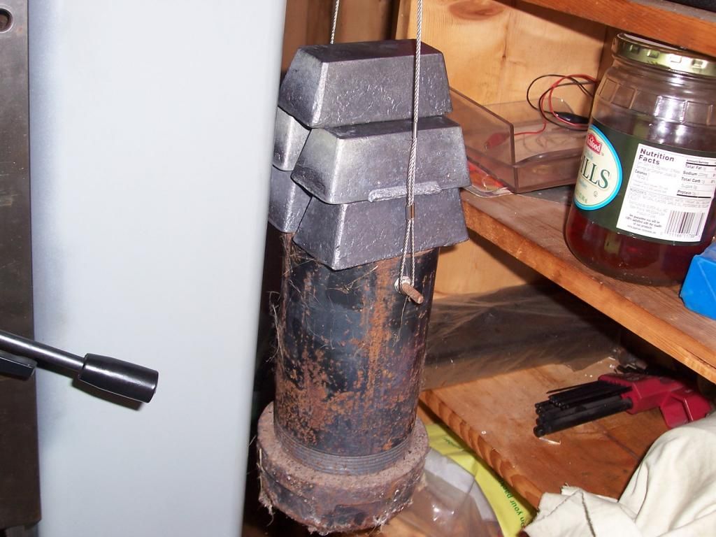
..and finally the crucible with 25lbs of lead stacked on it, with this amount of weight the mill head feels almost weighless when raising or lowering it.


Next I have dust off the furnace and melt the lead into the crucible and make some new cable attachments for the crucible.

Thats all I have for now, thanks for reading.

Steve.
 

Latest posts

Back
Top