A while back I posted plans (in the downloads section) for a single cylinder double acting version of my magnetically sprung V4 wobbler for anyone interested in a relatively simple first build.
I normally only post plans of things I have actually built but in this case it was a derivative so it should be fine.
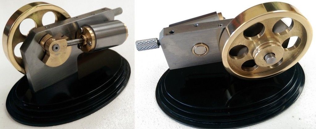
However my conscience nagged at me and I finally got around to building it :-

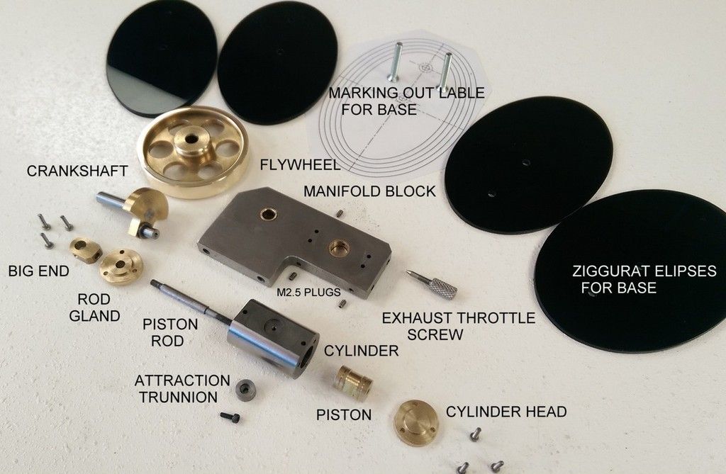
Still utilising the magnetic spring concept it has a fairly low parts count most of which are easy to make.

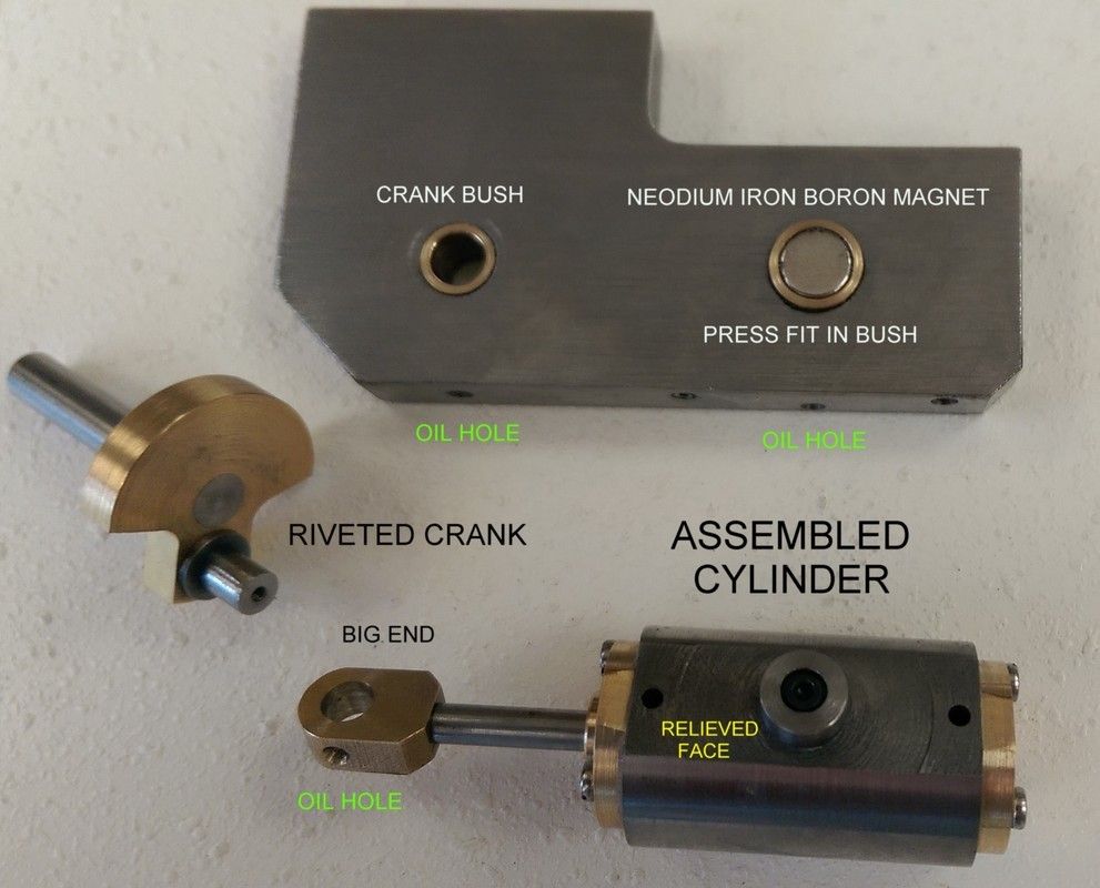
The crank was hand riveted together – I don’t know why but I enjoy joining bits with a hammer.
Using self adhesive 1:1 prints is my favourite marking out method for non-critical parts - I strongly suspect my printer is more accurate than my marking out in any case.

All in all it took about 16 hours to build.
And a video of it running.

(can someone tell me how to post the URL that the image appears ? - thanks Cogsy - next post)
I made the cylinder out of CI and the piston out of brass – in the plans it is the other way around.
To amuse my grandson I originally made the cylinder parts out of acrylic but that developed cracks from various points of stress and was abandoned.
Since I already had the piston in brass I made the cylinder of CI. It has a reamed bore of 10mm and the piston was lapped in from a tight fit using polishing compound.
To ensure concentricity of the piston and rod the piston was mounted on the rod (locktite) and trimmed to a tight fit in the cylinder.
Obviously if the gland end cylinder head or the piston/rod assembly are not concentric then you are going to have binding issues – particularly at the end of the stroke.
The Ø8x5 Niobium magnet is a perfect press fit in a reamed hole (seems to be deliberate sizing of all round NIB’s) – I extended the bush 1mm out the back to the setting distance marked on the plans for the magnet position which made pushing it into position that much easier.
Everything is metal to metal – no glands – but sealant was used on all static joints & grubscrew plugs.
At Ø10 bore x 15mm stroke its not exactly a workhorse – but you can goose it up 40% to a Ø12 bore if you increase the end cap screw hole PCD from Ø14 to Ø15 you can also open up the port size from Ø2 to Ø2.5 or even Ø3 at which point the ports start to overlap.
The plans also contain options for single acting as well as an optional "O" ring piston rod seal (which I didn't use).
The plans don't have the exhaust throttle - but that is fairly self evident and you need to tap the M3 ports deeper and remove its cross drill M2.5 plug.
The motor is reversed by swopping inlet and exhaust ports.
Regards,
Ken
I normally only post plans of things I have actually built but in this case it was a derivative so it should be fine.
However my conscience nagged at me and I finally got around to building it :-

Still utilising the magnetic spring concept it has a fairly low parts count most of which are easy to make.

The crank was hand riveted together – I don’t know why but I enjoy joining bits with a hammer.
Using self adhesive 1:1 prints is my favourite marking out method for non-critical parts - I strongly suspect my printer is more accurate than my marking out in any case.

All in all it took about 16 hours to build.
And a video of it running.
(can someone tell me how to post the URL that the image appears ? - thanks Cogsy - next post)
I made the cylinder out of CI and the piston out of brass – in the plans it is the other way around.
To amuse my grandson I originally made the cylinder parts out of acrylic but that developed cracks from various points of stress and was abandoned.
Since I already had the piston in brass I made the cylinder of CI. It has a reamed bore of 10mm and the piston was lapped in from a tight fit using polishing compound.
To ensure concentricity of the piston and rod the piston was mounted on the rod (locktite) and trimmed to a tight fit in the cylinder.
Obviously if the gland end cylinder head or the piston/rod assembly are not concentric then you are going to have binding issues – particularly at the end of the stroke.
The Ø8x5 Niobium magnet is a perfect press fit in a reamed hole (seems to be deliberate sizing of all round NIB’s) – I extended the bush 1mm out the back to the setting distance marked on the plans for the magnet position which made pushing it into position that much easier.
Everything is metal to metal – no glands – but sealant was used on all static joints & grubscrew plugs.
At Ø10 bore x 15mm stroke its not exactly a workhorse – but you can goose it up 40% to a Ø12 bore if you increase the end cap screw hole PCD from Ø14 to Ø15 you can also open up the port size from Ø2 to Ø2.5 or even Ø3 at which point the ports start to overlap.
The plans also contain options for single acting as well as an optional "O" ring piston rod seal (which I didn't use).
The plans don't have the exhaust throttle - but that is fairly self evident and you need to tap the M3 ports deeper and remove its cross drill M2.5 plug.
The motor is reversed by swopping inlet and exhaust ports.
Regards,
Ken


