


joco-nz
Well-Known Member
- Joined
- Feb 21, 2016
- Messages
- 568
- Reaction score
- 209
The next stage of the lathe stand evolution is well on its way - the Coolant System. Central to this is a tank. But not just any old tank, a custom built aluminium one with a bit of bling for a good measure.
I've been pottering away at things for a whee while doing things as I can in between other distractions. So there are a LOT of pics in this post as I have been building them up over the course of the build.
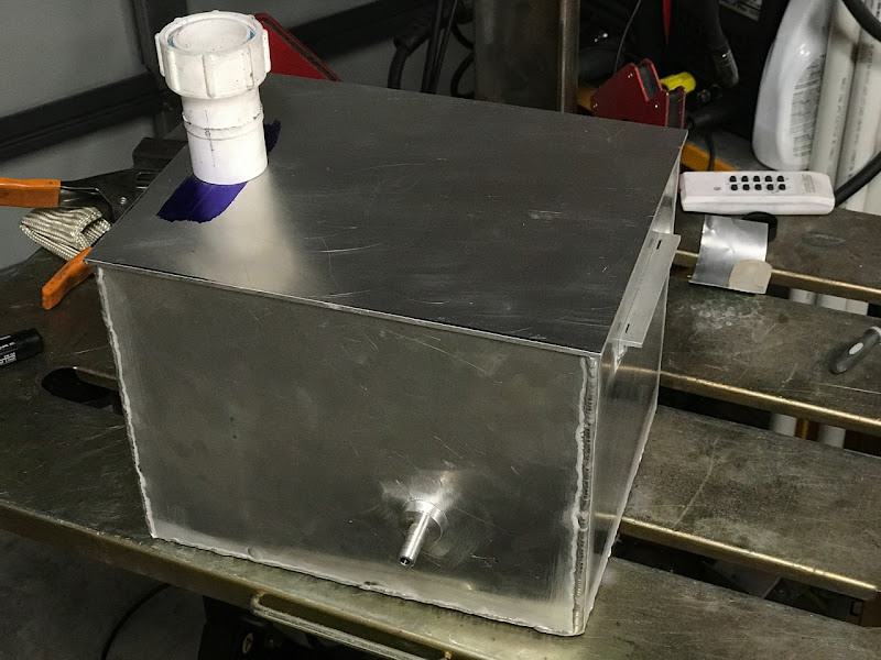
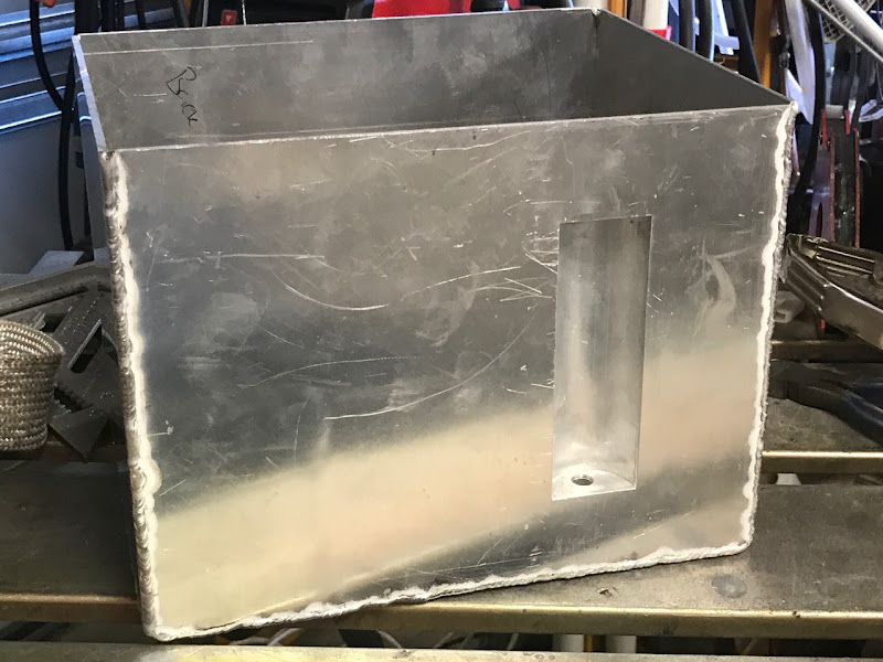
This is a pic of the coolant tank for the bandsaw. It's nearly done but gives an idea of what the general target will be. However I have added some refinements to lathe's tank.
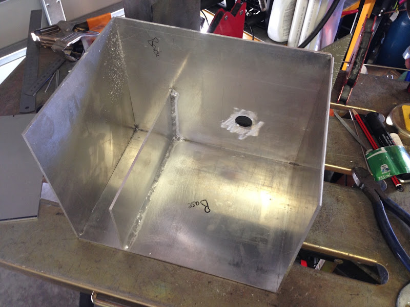
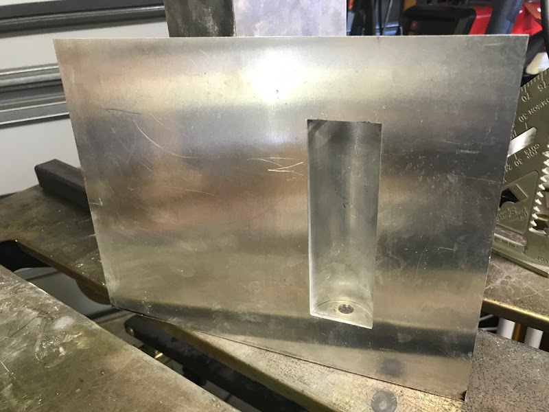
Early build progress. Panels cut up and inital tacking in place for some of them and the weir welded in. You can also see the hole drilled for the pump exit. I'm using a 12V marine bilge pump which has a 19mm ID exit fitting. The hole here is 25mm and will have a custom aliuminum fitting turned from 1" stock then welded into place.
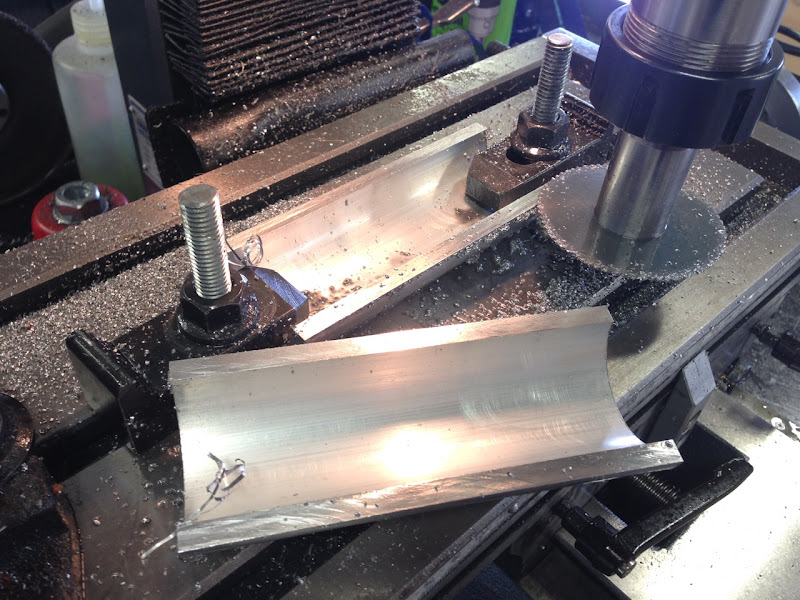
At this stage I got some material from a mate to make the recess/alcove for a fluid level sight guage. This is the end result of the first use of my slitting saw arbor.
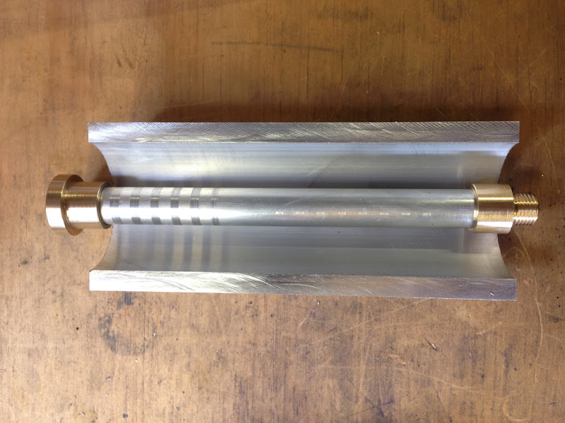
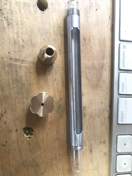
I'm using some 12mm aliuminium tube as a prototype piece with the brass fittings I made on the ends. At this time I was still waiting for brass tube to arrive.
The glass tubing I got from a local NZ smoking supplier called Wicked Habits. I bet they never thought their glass tubing would get used like this. You can see I tweaked the top fitting so it was easier to grip. I also eperimented with cutting the sight slot. Learned the right way to do that before screwing up the more expensive brass.
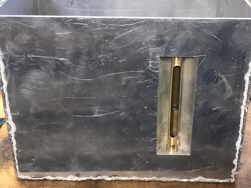
The alcove made with top/bottoms welded in place and eveything all cleaned up. These pics were taken pre the scolloping being done on the top brass fitting.
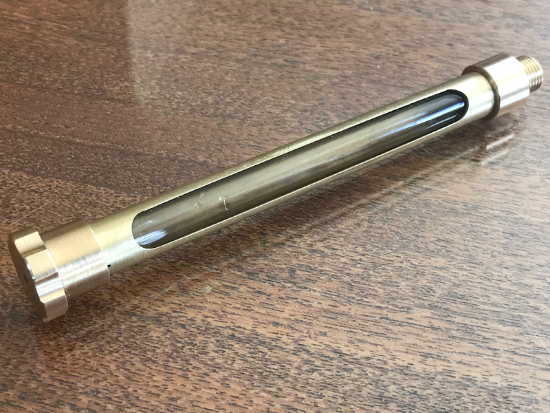
At last the brass tubing has arrived and I can make the tube to the correct length and slot it so as to get a good finish on each end.
Glass tube cut to correct length. What is not visible and I forgot to take a photo is that there is an O-Ring between the glass and the bottom brass fitting to act as a fluid seal. There is also one at the top to act as a compression buffer when screwing down on the glass tube.
Cutting out the window in the side panel. At this point I was looking around the workshop trying to figure out where I could place a scrollsaw.
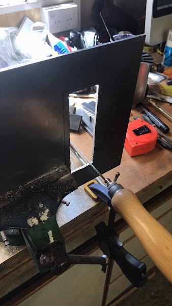
Used some big ass angle iron I had left over to act as a filing guide. Worked really well and ended up making nice straight and smooth sides to the window.
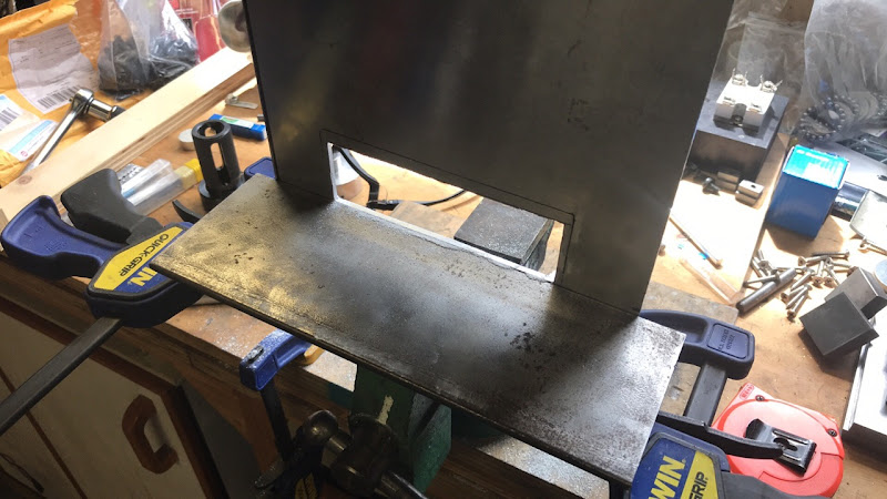
Tacked in place - looks pretty reasonable I think.
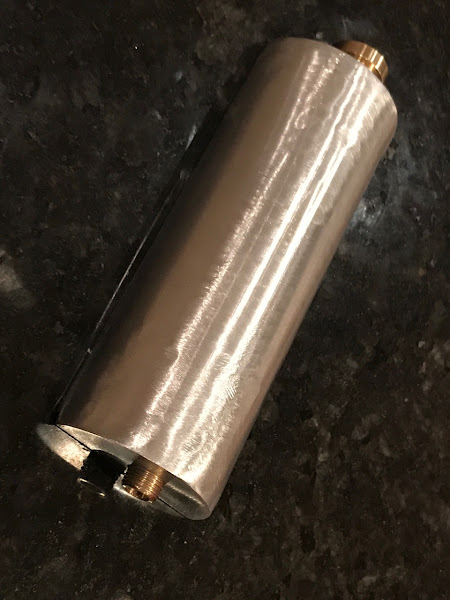
The tank starting to come to gether. All welded up.
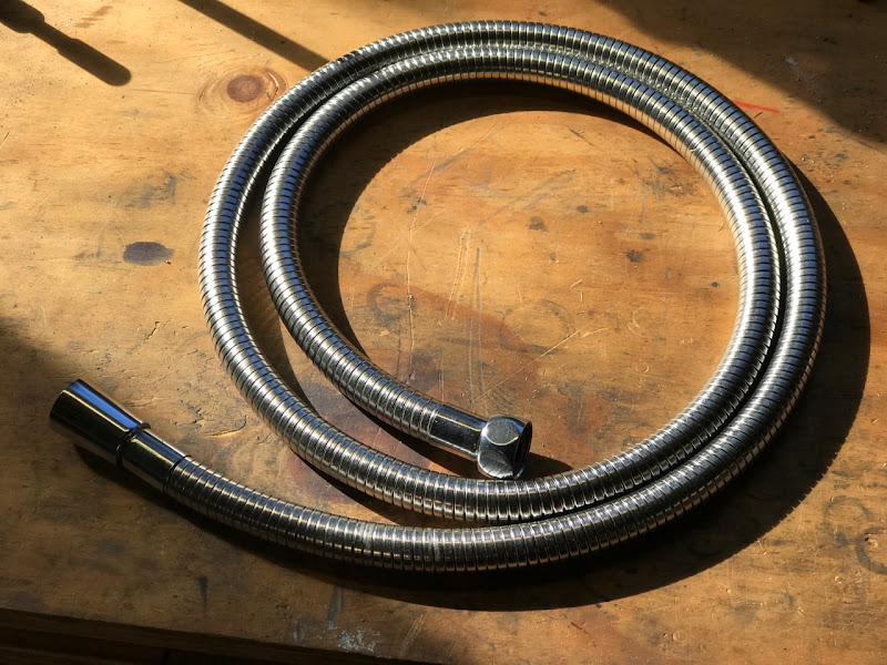
This is the hose I am going to use to get the coolant to the flexible segmented coolant pipe on the lathe. I wanted it to be "armoured" given it would be subject to sharp swarf. This is just a shower hose from a big box DIY store (Bunnings in my case). Hopefully the internal tbe will cope with what is going to be put through it. Time will tell.
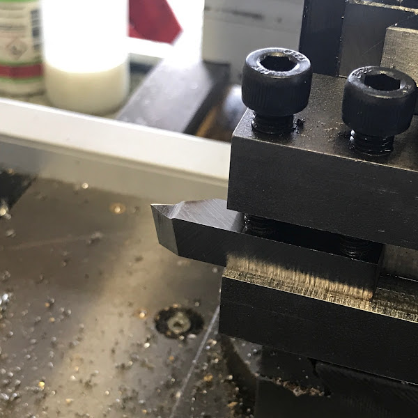
An important point is that the fittings on this are BSPP 1/2" 14tpi. Got to love how in a metric country a big chunk of our plumbing is still imperial. Anyway, I didn't have a 55deg Whitworth threading tool. Time to deal with that problem ... "off camera a tool is ground".
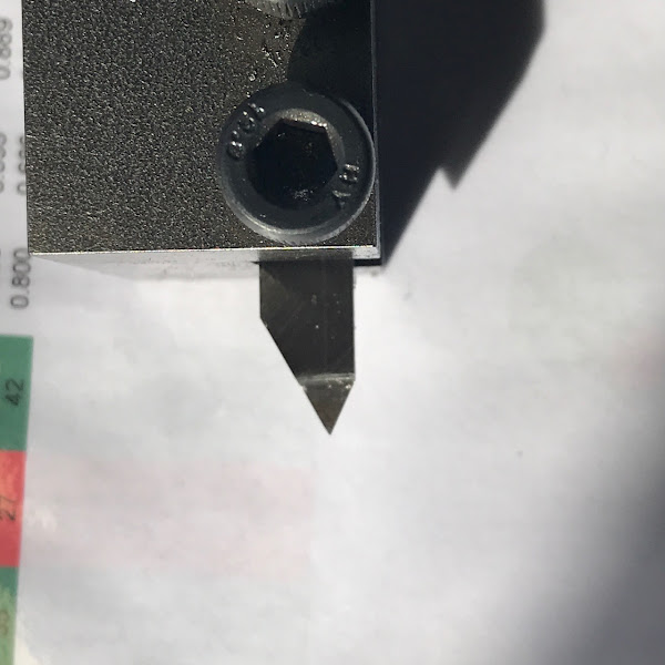
Lathe gearing changed for the 14tpi threading. Since my lathe has a metric lead screw I had to do everything from here with the half-nut always engaged. I still used the method of keeping the topslide parallel to the work. With a 3-axis DRO I love that method. Initial scratch test is good.
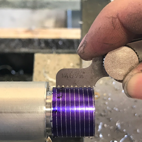
Thread cut and test fit is "thumbs up".
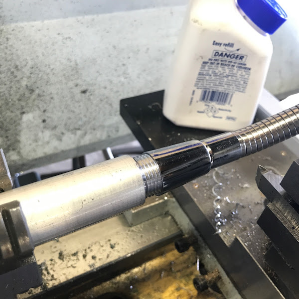
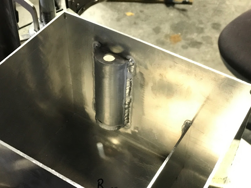
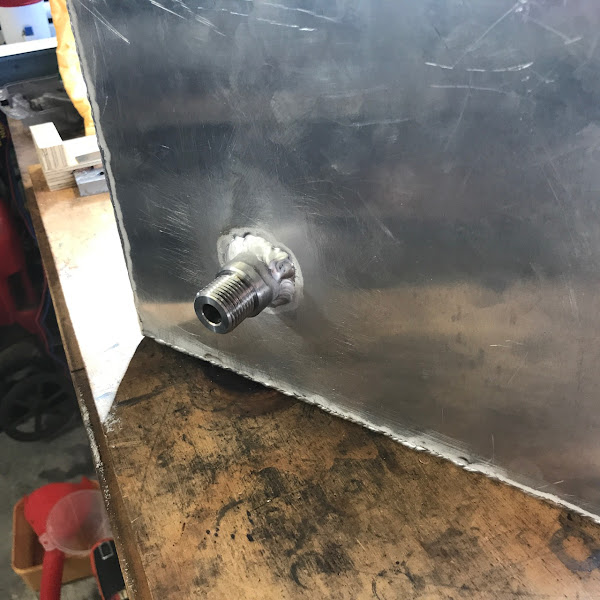
The resultant part is fitted and welded into place. I really need to learn to blast big chunks of ali with a propane flame to preheat them. This was a bugger to welded until it heated up.
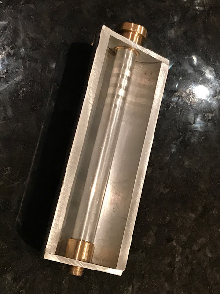
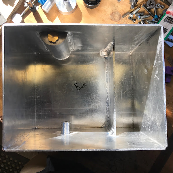
Looking down into the tank. Welding the weir all the way around was not fun. In hindsight just tacking it would have been fine then using some heavy duty marine grade sealant if I was really keen to properly seal it. It's really just to keep the metal particles from getting into the main body of the tank.
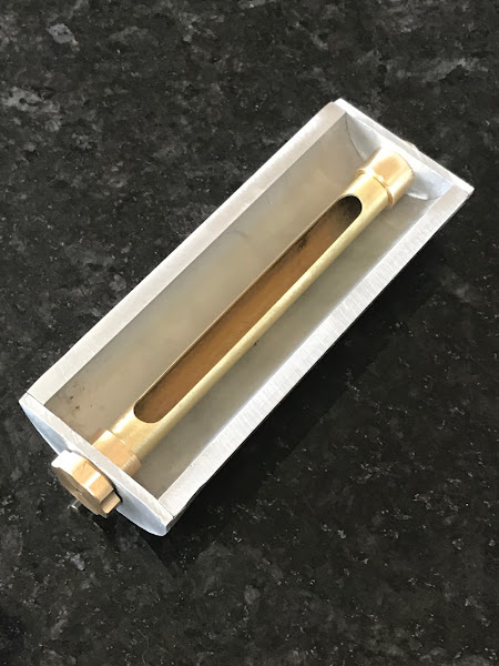
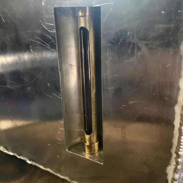
Gratuitous closeup of the sight guage, cose I could and what is one more photo?
Water in tank. I left the tank like this over night and no leaks anywhere. Very happy with that.
Next steps ...
- maybe some handles on the tank, just a few solid tack welded. No need to do full welds like I did on the bandsaw tank
- lid
- polishing the tank up
- plumbing that allows the lathe tray to be removed without having to undo things
- pump install
- 12v power supply for pump install
- switching system near the lathe controls
- fittings for the lathe cross slide
- other stuff I havent thought of yet
I've been pottering away at things for a whee while doing things as I can in between other distractions. So there are a LOT of pics in this post as I have been building them up over the course of the build.
This is a pic of the coolant tank for the bandsaw. It's nearly done but gives an idea of what the general target will be. However I have added some refinements to lathe's tank.
Early build progress. Panels cut up and inital tacking in place for some of them and the weir welded in. You can also see the hole drilled for the pump exit. I'm using a 12V marine bilge pump which has a 19mm ID exit fitting. The hole here is 25mm and will have a custom aliuminum fitting turned from 1" stock then welded into place.
At this stage I got some material from a mate to make the recess/alcove for a fluid level sight guage. This is the end result of the first use of my slitting saw arbor.
I'm using some 12mm aliuminium tube as a prototype piece with the brass fittings I made on the ends. At this time I was still waiting for brass tube to arrive.
The glass tubing I got from a local NZ smoking supplier called Wicked Habits. I bet they never thought their glass tubing would get used like this. You can see I tweaked the top fitting so it was easier to grip. I also eperimented with cutting the sight slot. Learned the right way to do that before screwing up the more expensive brass.
The alcove made with top/bottoms welded in place and eveything all cleaned up. These pics were taken pre the scolloping being done on the top brass fitting.
At last the brass tubing has arrived and I can make the tube to the correct length and slot it so as to get a good finish on each end.
Glass tube cut to correct length. What is not visible and I forgot to take a photo is that there is an O-Ring between the glass and the bottom brass fitting to act as a fluid seal. There is also one at the top to act as a compression buffer when screwing down on the glass tube.
Cutting out the window in the side panel. At this point I was looking around the workshop trying to figure out where I could place a scrollsaw.
Used some big ass angle iron I had left over to act as a filing guide. Worked really well and ended up making nice straight and smooth sides to the window.
Tacked in place - looks pretty reasonable I think.
The tank starting to come to gether. All welded up.
This is the hose I am going to use to get the coolant to the flexible segmented coolant pipe on the lathe. I wanted it to be "armoured" given it would be subject to sharp swarf. This is just a shower hose from a big box DIY store (Bunnings in my case). Hopefully the internal tbe will cope with what is going to be put through it. Time will tell.
An important point is that the fittings on this are BSPP 1/2" 14tpi. Got to love how in a metric country a big chunk of our plumbing is still imperial. Anyway, I didn't have a 55deg Whitworth threading tool. Time to deal with that problem ... "off camera a tool is ground".
Lathe gearing changed for the 14tpi threading. Since my lathe has a metric lead screw I had to do everything from here with the half-nut always engaged. I still used the method of keeping the topslide parallel to the work. With a 3-axis DRO I love that method. Initial scratch test is good.
Thread cut and test fit is "thumbs up".
The resultant part is fitted and welded into place. I really need to learn to blast big chunks of ali with a propane flame to preheat them. This was a bugger to welded until it heated up.
Looking down into the tank. Welding the weir all the way around was not fun. In hindsight just tacking it would have been fine then using some heavy duty marine grade sealant if I was really keen to properly seal it. It's really just to keep the metal particles from getting into the main body of the tank.
Gratuitous closeup of the sight guage, cose I could and what is one more photo?
Water in tank. I left the tank like this over night and no leaks anywhere. Very happy with that.
Next steps ...
- maybe some handles on the tank, just a few solid tack welded. No need to do full welds like I did on the bandsaw tank
- lid
- polishing the tank up
- plumbing that allows the lathe tray to be removed without having to undo things
- pump install
- 12v power supply for pump install
- switching system near the lathe controls
- fittings for the lathe cross slide
- other stuff I havent thought of yet
")