Accurate cross holes - without a jig.

Home Model Engine Machinist Forum

Help Support Home Model Engine Machinist Forum:

This site may earn a commission from merchant affiliate links, including eBay, Amazon, and others.

lemelman

Well-Known Member
Joined
Apr 2, 2012
Messages
84
Reaction score
18
Here's an old tip for drilling cross holes accurately, without a jig.
Mount the work-piece in the vice as usual, put a pointed rod in the drill chuck (a small centre drill will do, but is slightly less accurate), and balance a thin strip of metal on the work-piece; a steel rule is perfect.

Carefully lower the chuck to gently pinch the rule between the work-piece and the pointed rod as shown in the photo. The chances are that the rule will tilt because the pointed rod is not over the centre of the work-piece. Move the work-piece until the rule is horizontal (see photo) - it should be easy to do this accurately by eye to less than 0.20 degrees if you line it up to something known to be horizontal.
When satisfied, replace the pointed rod with a centre drill and start drilling.

The third photo shows the result of drilling a 6.3mm rod with 4.5mm drill. A drill that is large compared to the work-piece highlights any inaccuracy.

The last picture shows how the error "O" is affected by the tilt "A" of the rule. Since Sin(0.2) = .0035, the offset error would be about 1.7 thousandths of the diameter of the work-piece.

X-Drill1.jpg


X-Drill2.jpg


X-Drill5.jpg


X-Drill.jpg
 
Thanks for that Gary. A well deserved first Karma point :bow:
 
Heh :) I was taught the same trick for getting lathe tool on the centerline of the part, but never thought to use it horizontally for locating a drill. I like it!

 
That is great! thanks. It also solved a bunch of other related work-holding problems for me. 1 picture easily worth 1,000 words. Or, in my case, 2 hours of messing with the mill trying to figure out how to do something that turns out to be ridiculously easy :)
 
Another way is to mount the round part vertical in the vice. Sweep the diameter with a dial indicator until your dead on center. Then, lay the part down in the vice. Your on center in the Y axis.....adjust your X only for the axial position and go.

Dave
 
steamer said:
Another way is to mount the round part vertical in the vice. Sweep the diameter with a dial indicator until your dead on center. Then, lay the part down in the vice. Your on center in the Y axis.....adjust your X only for the axial position and go.

Or, if your geometry permits, mount the work in the vise such that a small portion of the jaws aren't grasping anything. Use your indicator/edge finder to find the middle of this gap. In effect you're using your vise jaws as improvised caliper jaws.
 
That steel rule trick works also for aligning the rotary table with the spindle.
Another way of centering the rod horizontal into the vice, using the dro, is by chucking a straight rod in the mill: You touch one side and zero the dro,
then halve the reading You get when touching the other side.
If You know the exact diameter of the workpiece and touching rod, touching one side would be enough.

Marcello
 
mklotz said:
Or, if your geometry permits, mount the work in the vise such that a small portion of the jaws aren't grasping anything. Use your indicator/edge finder to find the middle of this gap. In effect you're using your vise jaws as improvised caliper jaws.

That is the absolutely the way to go if you have a DRO
Easy Peasy
Dave
 
i saw this somewhere but using a razor blade instead (razor blade is more flimsy so to be more accurate) it said. any who good tip.
 
This is a great method and works well. I have one of those cheap 'n cheerful cross-vises mounted on my drill press, and regularly use this method when cross-drilling round stock on the DP. The cross-vise makes things easy to adjust.

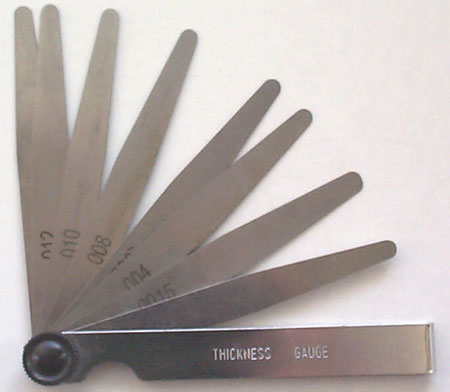
At one point I used my 6" rule for this, but ran into problems with smaller stock (less than 1/2" / 12mm diameter). The measurement engravings on a rule can influence the "reading" if one is not careful to miss those in the pressure area - so instead of using the rule, I now use cheap feeler-gauge blades for that.

I also test with the drill chuck turned through 90o turns; if the drill tip or the drill spindle is slightly off-center I just look for the maximum deflections through a full 360o rotation If the plate deflects one way, and after a 180orotation the other way, you're on center.

One last thing; I try and balance the plate on the workpiece a bit before I touch it with the pointy bit/drill in the chuck. If the bit of plate is not relatively balanced, the "reading" can be a bit skewed - so to speak.

Kind regards, Arnold

Oh, and the feeler gauge blades are also very useful as shims for setting lathe toolbit height ;) - for anyone that does not know what the feeler gauge set looks like, here's an image - as it looks like before I take it apart to use the separate blades:
thickness_gauge.jpg
 
If you use two different methods and they disagree by .001", which one is right? and who cares? Its good to have more than one way to go.

Jerry
 
Here's one I use: Mount a v-block in the vise and use a test indicator to indicate the "v" of the v-block.

I've also clamped the v-block to the table and indicated one side to align to the axis as if it were a vise. Then I indicated the "v" to get the center of the v-block as mentioned above.

Once the v-block is centered the bar is clamped in the v-block; the edge is picked up; the dimension is stepped off and the hole is drilled.

It's easy, fast and accurate.


For small stuff I came up with this idea: http://www.homemodelenginemachinist.com/index.php?topic=14877.0
The bad pictures don't illustrate the idea well and it is a fixture. Basically, throw a block of aluminum in the mill. Mill the top surface flat. Drill and tap holes for hold downs. Use a center drill to machine a small groove in the block. Don't touch whatever axis the groove is cut in. Place the bar in the groove and clamp it. Step off from the end and drill the hole.

-Bob
 
Back
Top