A Webster moment---

Home Model Engine Machinist Forum

Help Support Home Model Engine Machinist Forum:

This site may earn a commission from merchant affiliate links, including eBay, Amazon, and others.

Brian Rupnow

Design Engineer
Project of the Month Winner
Joined
May 23, 2008
Messages
15,250
Reaction score
8,529
Location
Barrie, Ontario, Canada
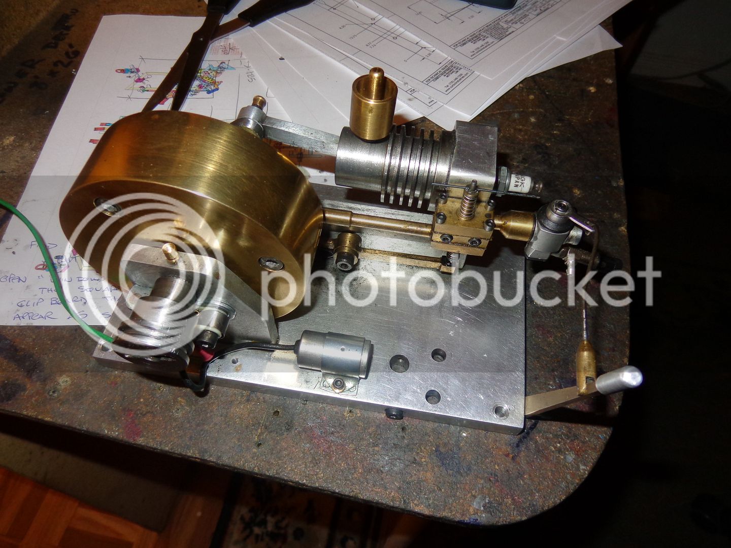
This past weekend I decided to fire up my fat flywheeled Webster that I built a few years ago. I tried EVERYTHING that I know how to do to get it started (And thats quite a fair bit), but there was no way it would run. I checked the coil---I checked the points---I checked the battery---I checked the sparkplug---I twiddled (Yes, a highly technical term) the carburetor seven ways from Sunday. Finally I gave up, figuring that the model engine Gods hated me. That was the only reason I could come up with. Tonight I reluctantly took another look at it. Hey---Son of a gun---When I stopped cranking it with my electric drill, the crankshaft stopped.---But the flywheel kept on going. Somehow, that .093" dowel pin that holds the flywheel in place has sheared in two places--and the timing gear is attached to the side of the flywheel. The probability of getting everything lined up to the point where I can drive that dowel pin thru and out is slim to none. I think that engine will go back up on the shelf for the foreseeable future, or until I have an epiphany about how to get the dowel pin out.
 
Maybe just press the crank off the flywheel??
That's the answer. The pin is broken so you don't need to remove it before removing the flywheel from the shaft. After the flywheel if off it's a simple matter to punch out the broken peaces of the pin from the flywheel and shaft.
 
The fat flywheeled Webster rides again!!! I got VERY lucky. The pin I had used the first time around was a split pin with a hole down the center. I had a package of sewing needles left over from my carburetor needle valve making adventure, and one of the needles was small enough to fit through the center hole of the split pin. I pushed the pin in lightly from one side of the flywheel until it bottomed out against the crankshaft, then turned the crankshaft slowly until the pin slipped into the broken section of split pin. Once I had everything aligned, some very careful tapping with a very small drift punch removed the 3 broken pieces of split pin. I had a 50% chance of it being in the correct rotational alignment, so I tapped in a new split pin. I then checked the valve and spark timing by rotating the flywheel (which has the small timing gear attached to the side of it) until I decided I had got it right the first try. Took it out to the bench in the big garage, hooked up the gas line and coil wire, gave it a spin, and away it went!!! that carb is a Traxxas #4033 and seems to be the perfect size for engines of this relative bore and stroke size.---They cost about $40.00----Brian
 
Boy will i be happy when mine makes some nosie like yours.
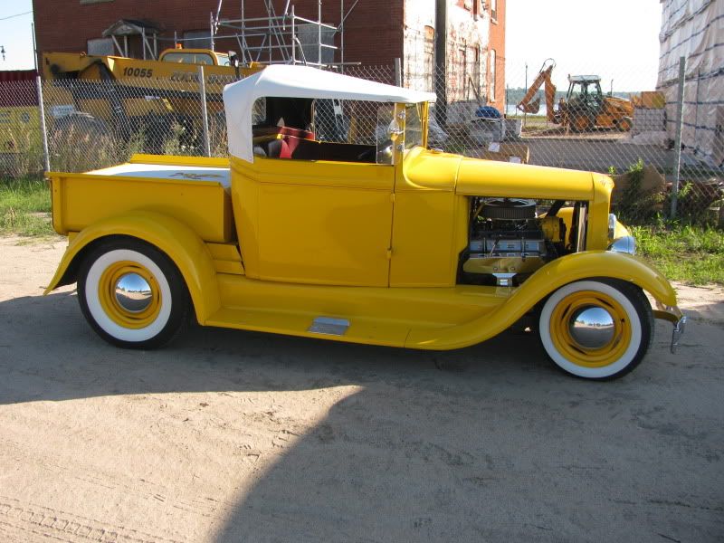
Cant help but to notice the yellow with the wide white walls in the back ground. What you hiding there?
 
Boy will i be happy when mine makes some nosie like yours.
Cant help but to notice the yellow with the wide white walls in the back ground. What you hiding there?
That's my 1931 Ford roadster pickup that I built about 8 or 9 years ago. I'm running a small block Chev engine in it. I was heavily involved with drag racing and hotrod building pretty well all my life until about 5 years ago when my arthritis got so bad I couldn't get up and down off the concrete floor anymore, which is required an average of two million times when building these things. That's why I switched to building small engines. The hotrod is my daily driver fro May to October. I have a new Ranger pickup that doesn't get driven at all in the summer months unless its raining or exceptionally cold outside.
 
SWEET!!! Im currently building a 40 ford coupe with my Father, this weekend hope to fire it up for the first time. Its has a 350-350 with 9" rear. Still waiting on a couple of things to show up, then off to the exhaust shop...

40 ford.jpg


350eng.jpg
 
Very nice coupe.--Love early hotrods, always have. For what its worth---I just hooked the Webster up to the sawmill and sawed a spruce board with it. By the end of the cut, the Webster was starting to get pretty hot. Those cooling fins are more about show than go. That's what I like about my hit and miss engines with the coolant reservoir. They run much, much cooler than an air cooled engine---and thanks to the hit and miss feature, they pump a lot of cooling air thru the cylinder during the "miss' cycle to carry off even more heat.
 
I had considered a deviation from the plans to help out the cooling. Either remove the fins and add an aluminum finned section to the cylinder or water cool it with an external plunger type pump driven by an eccentric. Right now just need to stay the course and get up and running. Then I will tinker and make changes.
 
I had considered a deviation from the plans to help out the cooling. Either remove the fins and add an aluminum finned section to the cylinder or water cool it with an external plunger type pump driven by an eccentric. Right now just need to stay the course and get up and running. Then I will tinker and make changes.

I was thinking about making the cooling fins a little larger in diameter (say increase the diameter by 1/4 or 3/8"), and then notching them for the frame, if necessary. Possibly cutting fins in the corners of the head. Do you guys think that will help any? I wonder if just running a small fan, blowing on the cylinder, would make a difference. Brian, had you had heat problems before running it under load?
 
remove the fins and add an aluminum finned section to the cylinder

I have read, in some thread here, a comment from a builder saying that, if the fins are not integral to the cylinder, the joint line between the cylinder and the fins decreases the heat transfer to the fins. No personal experience on this.
 
I had origonally cut my fins larger. It was not an attractive look at all.
 
I have read, in some thread here, a comment from a builder saying that, if the fins are not integral to the cylinder, the joint line between the cylinder and the fins decreases the heat transfer to the fins. No personal experience on this.

As a press fit it would be in full contact with the cylinder. I think you may be thinking of having an insulator between the head and the cylinder, like a paper gasket, that would reduce the heat transfer.....but a soild copper one would not.
 
I have extensive experience with heat transfer between two different pieces of metal i.e. cooling fins pressed on over a plain cylinder. Frankly, it doesn't work worth a damn. Even with copper based heat conductive paste between the two surfaces, it doesn't work worth a damn. I did a lot of this type of experimentation with permanent molds for die casting aluminum wheels when I worked with Volkswagen of Canada. If you build a water jacket with an open top like a reservoir and seal it to a plain finless cylinder with hi temp O-rings (as in Viton) then the reservoir of water will help immensely with cooling the engine for protracted runs, either freewheeling or under load.---Brian
 
Brian, is what your saying, a one piece steel cylinder with cooling fins would cool better than than one with pressed on aluminium fins of equal size? Or that it would make no difference?
Hmm may have to go liquid cooled....
 
Brian, is what your saying, a one piece steel cylinder with cooling fins would cool better than than one with pressed on aluminium fins of equal size? Or that it would make no difference?
Hmm may have to go liquid cooled....
A cylinder with pressed on fins will not cool even remotely close to what a cylinder with fins machined into the parent metal will. And neither will cool close to what a water jacket/reservoir of water will.
 
That seems very odd, you would think the aluminium fins would be better. Hmm think I need to do some research and educate myself on this. Thermal conductivity.........
 
Most people who build this engine only run it for 15 minutes or less at a time, so overheating doesn't become an issue. Its a wonderful little engine for first time i.c. builders. Its only when you run it for protracted periods of time or under a load that heat becomes an issue. If you build it with the fins cut into the cylinder, that's good. If you then add a cooling fan with an o-ring drive to blow onto the cylinder, that's even better. If you build it with a water reservoir or a "jacket" which water can be circulated through, that's about as good as it gets in terms of cooling for long runs or running under a load. However, the other side of the penny is that no fins at all are very bad, and a plain cylinder with cooling fins press fitted on, either individually or as a pre-machined "sleeve" is only marginally better. You simply don't get good enough thermal transfer to really do a good cooling job.
If you are just building this engine to see if you can, and only running it for 5 minutes at a time or less, then I don't suppose it matters much one way or another.
 
http://www.engineeringtoolbox.com/thermal-conductivity-metals-d_858.html
http://en.wikipedia.org/wiki/Thermal_contact_conductance#Thermal_boundary_conductance

Aluminum has a much higher heat transfer rate than steel or iron.......An aluminum cylinder with aluminum pressed on fins would have some loss over a solid machined piece, but a steel or iron cylinder with aluminum fins pressed on would cool better than a steel or iron one piece cylinder. Atleast thats what it looks like to me. Im really not sure if this would matter much at all given the size of the model engines in regaurds to the cooling surface area they have..
 

Latest posts

Back
Top