You are using an out of date browser. It may not display this or other websites correctly.
You should upgrade or use an alternative browser.
You should upgrade or use an alternative browser.
A new attempt at making piston rings
- Thread starter Brian Rupnow
- Start date

Help Support Home Model Engine Machinist Forum:
This site may earn a commission from merchant affiliate
links, including eBay, Amazon, and others.
- Joined
- Jun 24, 2010
- Messages
- 2,425
- Reaction score
- 959
I'm curious about the Trimble bolt selection. Actually he says 5/16-32 TPI. He used the same (cast iron) material for fixture but says (among other things) 'I doubt that this is very important'. Then 'the dowel & bolt are stainless steel so they wont lose all their strength as the cast iron does at its annealing temperature' and 'I think the material for the dowel and bolt is important' and 'there is no reason to to tighten the bolt more than finger tight'.
So how this collectively converges on a choosing a 5/16-32 TPI stainless bolt torqued to finger tight is above my pay grade, especially considering he wasn't fussy about the fixture material.
So how this collectively converges on a choosing a 5/16-32 TPI stainless bolt torqued to finger tight is above my pay grade, especially considering he wasn't fussy about the fixture material.
I read somewhere in all of my junk that Trimble got the thread pitch wrong. Fine threads don't like to turn after heat treat. He also contradicted himself on the type of material to use on the heat treat fixture.
- Joined
- Jun 24, 2010
- Messages
- 2,425
- Reaction score
- 959
Right you are - under the infamous SIC Errata. "Should read 5/16-8", "George would have used a coarser thread if there was one readily available".
- Joined
- Jun 24, 2010
- Messages
- 2,425
- Reaction score
- 959
It appears stainless has higher thermal coefficient of expansion (E-6 in/in). Which would infer... the bolt is growing slightly = loosening. But the dowel pin is growing = expanding (ever so slightly) at elevated temp??
303 stainless = 10.9
Cast iron = 5.8
4140 = 6.8
A36 = 6.5
table here, different units
https://www.rolledalloys.com/technical-resources/fabrication-information/thermal-expansion/
303 stainless = 10.9
Cast iron = 5.8
4140 = 6.8
A36 = 6.5
table here, different units
https://www.rolledalloys.com/technical-resources/fabrication-information/thermal-expansion/
Trimble used numbers in his calculations that are of unknown origin. They may be "constants", but if they are, I don't know what they refer to. If you have a spread sheet to do the calculations, where you just plug in the known values and the spread sheet kicks out the answers, then that's great. If you try and do it on a calculator, it's pretty iffy because you don't know what his numbers are referring to.

$99.99
$109.99
AmTech300 - Boiler Treatment Professional Strength (Rust Inhibitor For Outdoor Wood Boilers)
Alternative Heating & Supplies

$190.00
$254.99
Genmitsu CNC 3018-PRO Router Kit GRBL Control 3 Axis Plastic Acrylic PCB PVC Wood Carving Milling Engraving Machine, XYZ Working Area 300x180x45mm
SainSmart Official

$99.99
AHS Outdoor Wood Boiler Yearly Maintenance Kit with Water Treatment - ProTech 300 & Test Kit
Alternative Heating & Supplies

$59.99
Sunnytech Hot Air Stirling Engine Motor Model Educational Toy Electricity Generator Colorful LED (SC001)
stirlingtechonline

$403.09
DM14 Engine Build Kit, Metal Engine Build Model Great Metal Material for Engineer for Factory
Easoger Official

$519.19
$699.00
FoxAlien Masuter Pro CNC Router Machine, Upgraded 3-Axis Engraving All-Metal Milling Machine for Wood Acrylic MDF Nylon Carving Cutting
FoxAlien Official

$156.90 ($1.40 / oz)
Replacement Combustion Chamber Kit, Burnham V8 and V8H, 1-6 Sec, 108136-01, 1129
Lynn Manufacturing

$45.99
Sunnytech Mini Hot Air Stirling Engine Motor Model Educational Toy Kits Electricity HA001
stirlingtechonline

$94.99
$109.99
AHS Woodmaster 4400 Maintenance Kit for Outdoor Wood Boiler Treatment
Alternative Heating & Supplies

$188.98
TM NEXDYNAMI RE41157 Water Pump Compatible With/Replacement For/John Deere 6200 7400 6300 6600 6500 6400 7220 7600 7200 RE41157
VIVID MARKET CORPORATION

$39.99
$49.99
Sunnytech Low Temperature Stirling Engine Motor Steam Heat Education Model Toy Kit For mechanical skills (LT001)
stirlingtechonline
- Joined
- Jan 4, 2011
- Messages
- 1,418
- Reaction score
- 384
I am sure that a lot of folks would love to get Trimble on a forum like this and ask some questions. Primarily they would like to know what is critical and what is open to modifications. Things like how critical is dowel dimeter if other parts are changed accordingly, how critical is material, and how did he arrive at some of his calculations.
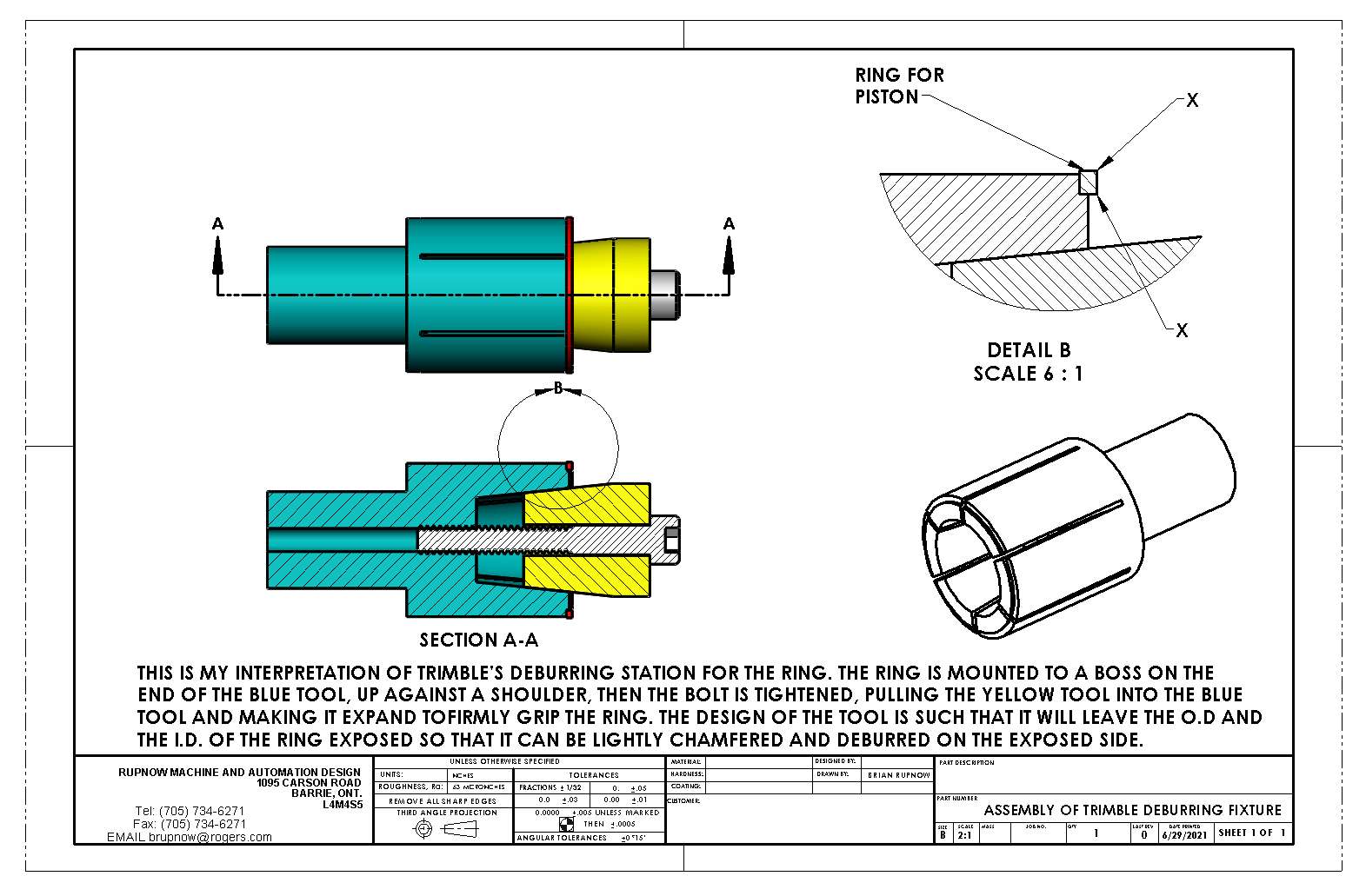
This is my interpretation of the Trimble deburring station. One side of the ring is chamfered and deburred before the ring is parted from the parent stock. The other side of the ring, after parting off will need deburring and chamfering. This is the station that allows you to do that. The good side of the ring is butted up tight to the shoulder on the blue piece, the the bolt is tightened to pull the yellow piece into the blue, causing it to expand and grip the ring, leaving the second side of the ring exposed so it can be deburred and chamfered.

That was going to be my suggestion if no one else suggested it. I have a Windows XP virtual machine (and a Windows 10 virtual machine) available on my Linux laptop - I use these on the rare occasions when I need to access something that is only available on Windows or on an old Windows platform.You could also create a virtual box and try that to install.
As I read the Trimble articles, and he talked about all the rings he made and tested in the V8, I had to wonder if he ever finished that engine....
I never saw anything about it running, other than external power, but maybe I missed that.
Doug
I never saw anything about it running, other than external power, but maybe I missed that.
Doug
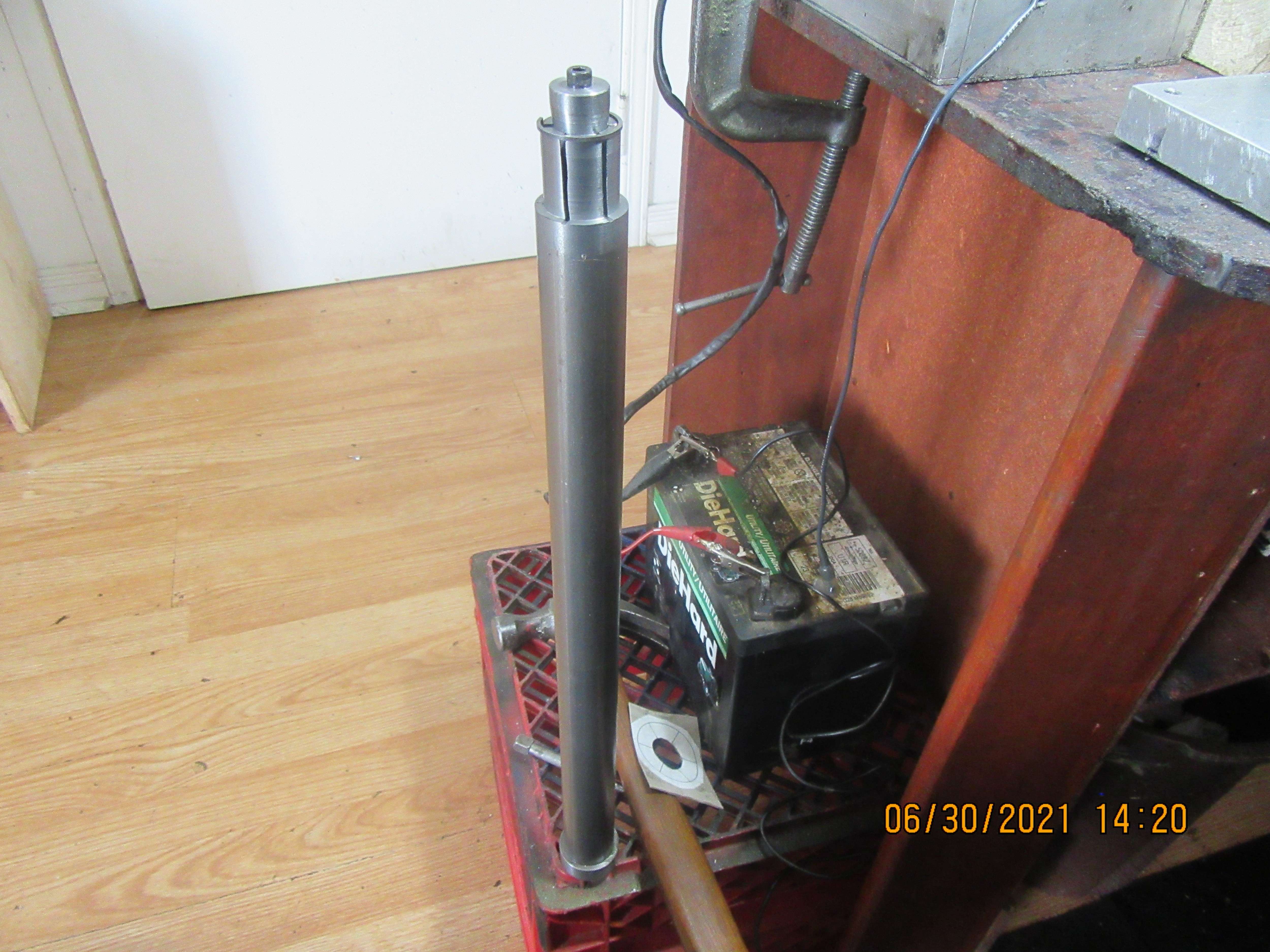
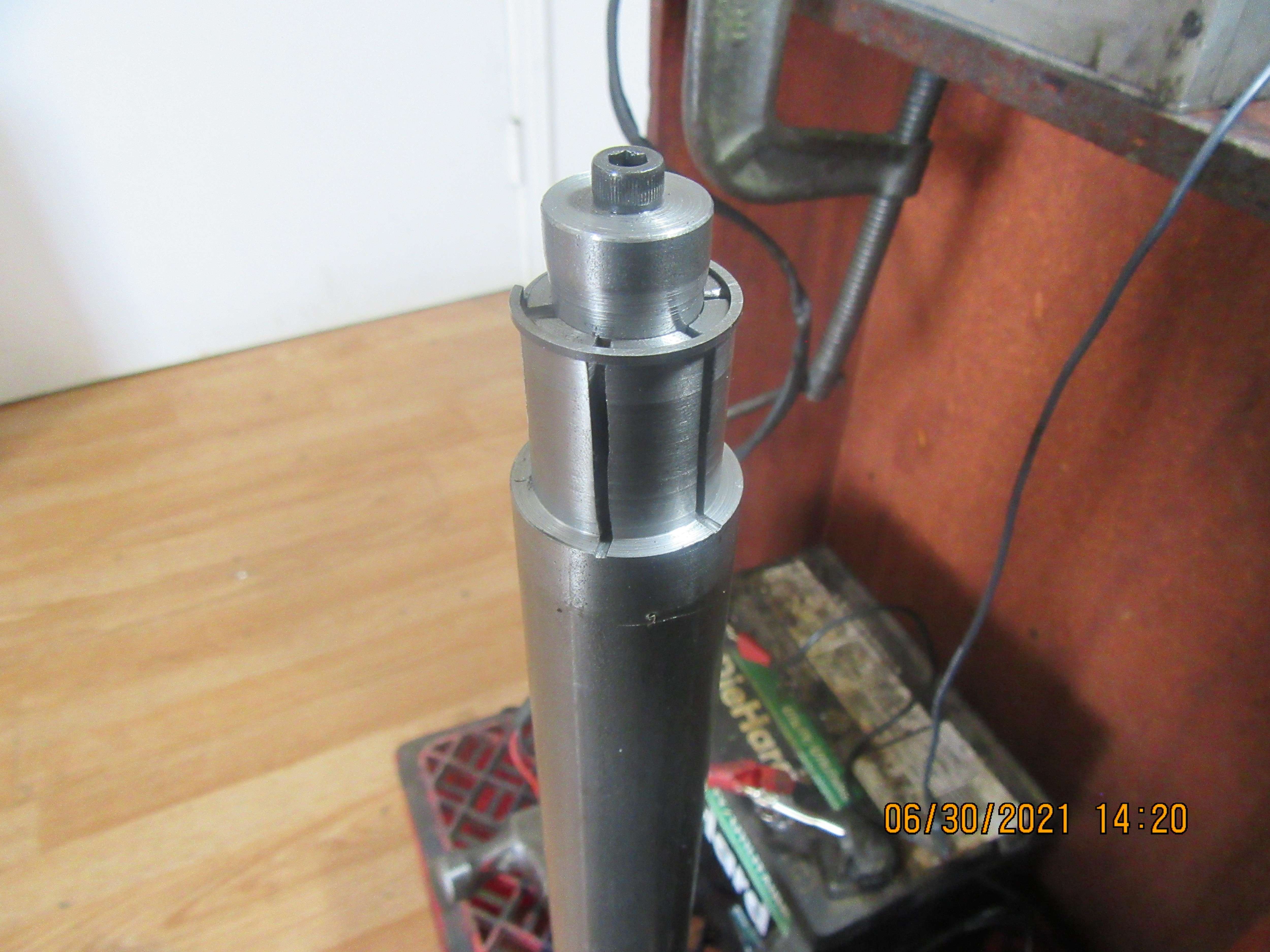
Here we have the internal expanding mandrel, which holds the ring while the "bad" side of the ring is deburred and chamfered. (The other side of the ring was chamfered and deburred before it was parted off from the parent stock). I even have a ring shown on the end of it, although that ring isn't the right ring, it's just one of the old rings I had around. You will notice that the main body of this tool is much, much longer than the solid model.---This is why---My 3 jaw chuck never can grip something twice in a row, without grabbing it a little differently. This shows up with a dial indicator, even if it's hard to see with the naked eye. So, my thoughts were, if I want to use this tool more than once, I should do something to guarantee that I always grip it the same way, in the same place. My lathe spindle is 1 1/2" thru the bore, so on the far end of this 1 1/4" diameter main body I have a ring of material 1.499" in diameter, and have the other end stamped 1, 2, and 3 to correspond with the chuck jaws. When installed, the ring of material is flush with the far end of the spindle. This brings me to a point where there are no more fixtures to build. All I need now is that damned fine India stone which is somewhere between Sweden and here. I am going to call "Terra Nova Steel and Iron inc. in Mississauga this afternoon and see if they will sell me a 12" length of Durabar to make rings from. I doubt very much that I need to do that, but I am not leaving any stone unturned in my quest to make working cast iron rings.


- Joined
- Dec 31, 2010
- Messages
- 812
- Reaction score
- 215
There is one more fixture that is not covered by Trimble but is pretty handy to have. After annealing, the sides of the rings need to be polished and possibly to bring the rings exact thickness to fit in your piston ring grooves. It's a puck of metal with a shallow pocket machined into the end - shallower than your ring is thick.
It's used as a handle to hold a ring while you polish the sides of the ring by hand pushing it around on a flat surface with wet/dry paper.
It's used as a handle to hold a ring while you polish the sides of the ring by hand pushing it around on a flat surface with wet/dry paper.
Last edited:
Dsage--I have that fixture already, left over from previous ring making adventures.
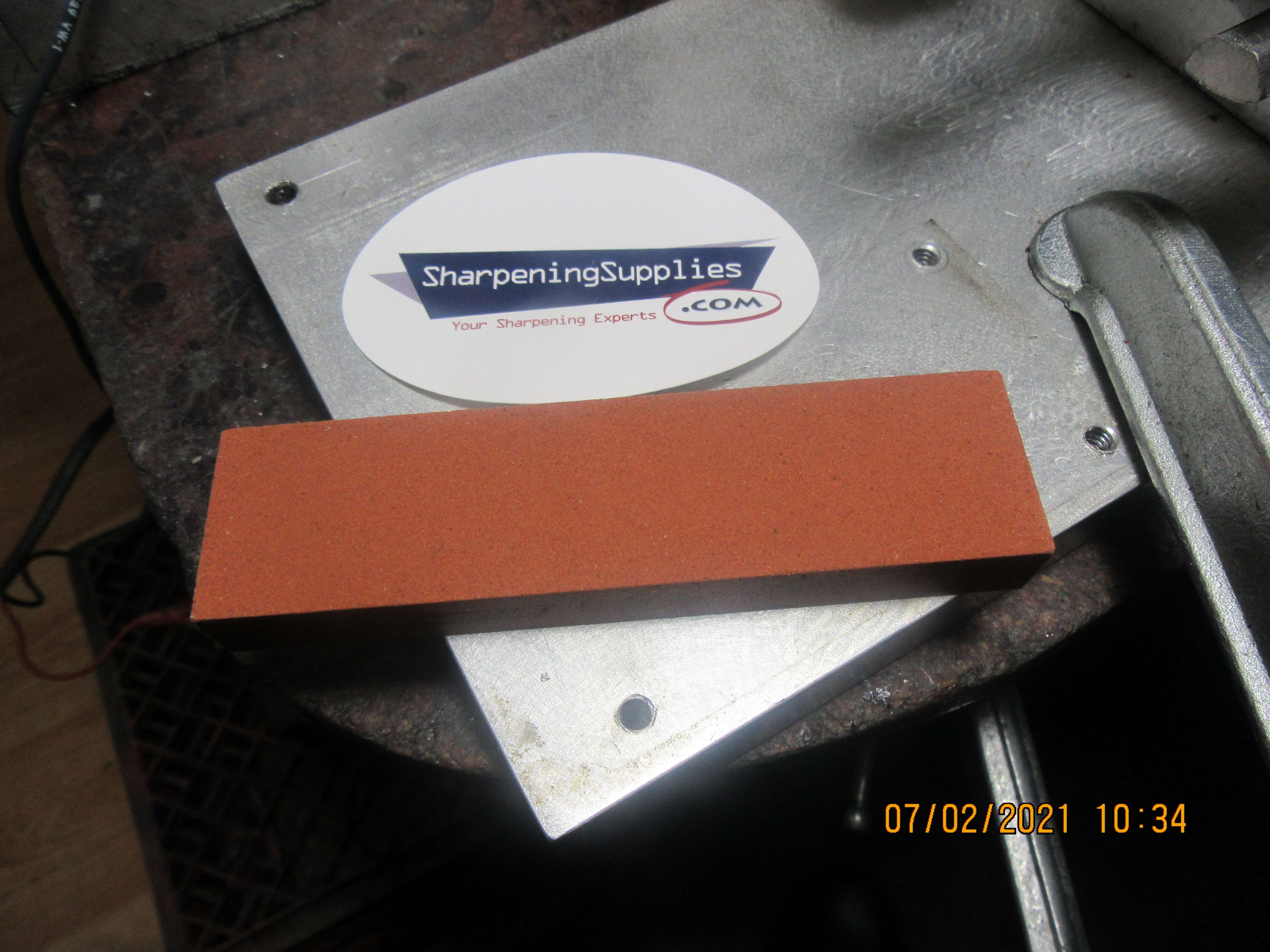
Today my "fine India stone" arrived in the mail. If it had been holding me up on a project I could get really ugly about how long it took to get here. However, it hasn't held me up, as I had three fixtures and a new piston to make before it would be needed anyways, and I just finished the third fixture yesterday. Now all that is left is to make the rings. Wish me luck!!!---Brian

I tried making cast iron rings, and found that it is not that difficult to do.
After a few practice rings, I was able to easily make some nice cast iron rings.
I have seen various methods for parting the rings.
The method I used was to place flat-nosed pliers immediately adjacent to each other on the ring, and rock them ever so slightly back and forth until the cast iron fatigues and breaks.
Then I lightly cleaned up the ends at the break.
Worked fine.
For low-rpm steam engine work, it is not much of a problem to get the correct ring clearances.
For a high-rpm model airplane engine with very tight tolerances, I guess a lot more care would need to be paid.
I leave a slight amount of clearance to allow for expansion due to steam.
I prefer cast iron rings because "they wear like iron", LOL, they are iron, but also because as a model builder, I love the challenge of trying to make the engines like they were made in the day, not that there is anything wrong with the modern materials.
Its like standing in front of Everest; do you ride the cable car up to the top, or get out the ropes and carabiners and start climbing?
Edit:
For now, I turn my rings to the same size as the bore (actually slightly smaller for expansion), and then expand the ring and heat it, to spring it out.
I have dabbled with making oversized rings that are sprung inwards and turned to final size, but that takes quite a bit more work, and I have not mastered that technique yet.
.
Second oldest grandkid just graduated from public school. She's a pretty girl.


So-----------Here we are again. A new batch of rings, made from fine grain grey cast iron. I used my "special grind" HSS grooving tool to part these rings off. Each ring is 0.044" wide, which leaves a small bit on each side for "clean up" on a sheet of 600 grit paper. I hit the numbers perfectly on the o.d. and the i.d. and made 8 rings, of which I only need two. My opinion on the "Fine India Stone" that I bought---It doesn't do anything that a piece of 220 grit paper held against a flat file won't do. I may have wasted my money buying it
but I'm trying to follow everything that Trimble suggests. Next step will be to mount each ring on the Trimble fixture and deburr/chamfer the side which was not deburred/chamfered before it was cut off from the parent stock. If these rings don't work, there is enough turned material on the "parent stock" to make new rings 0.045" thick, same as Trimble did.
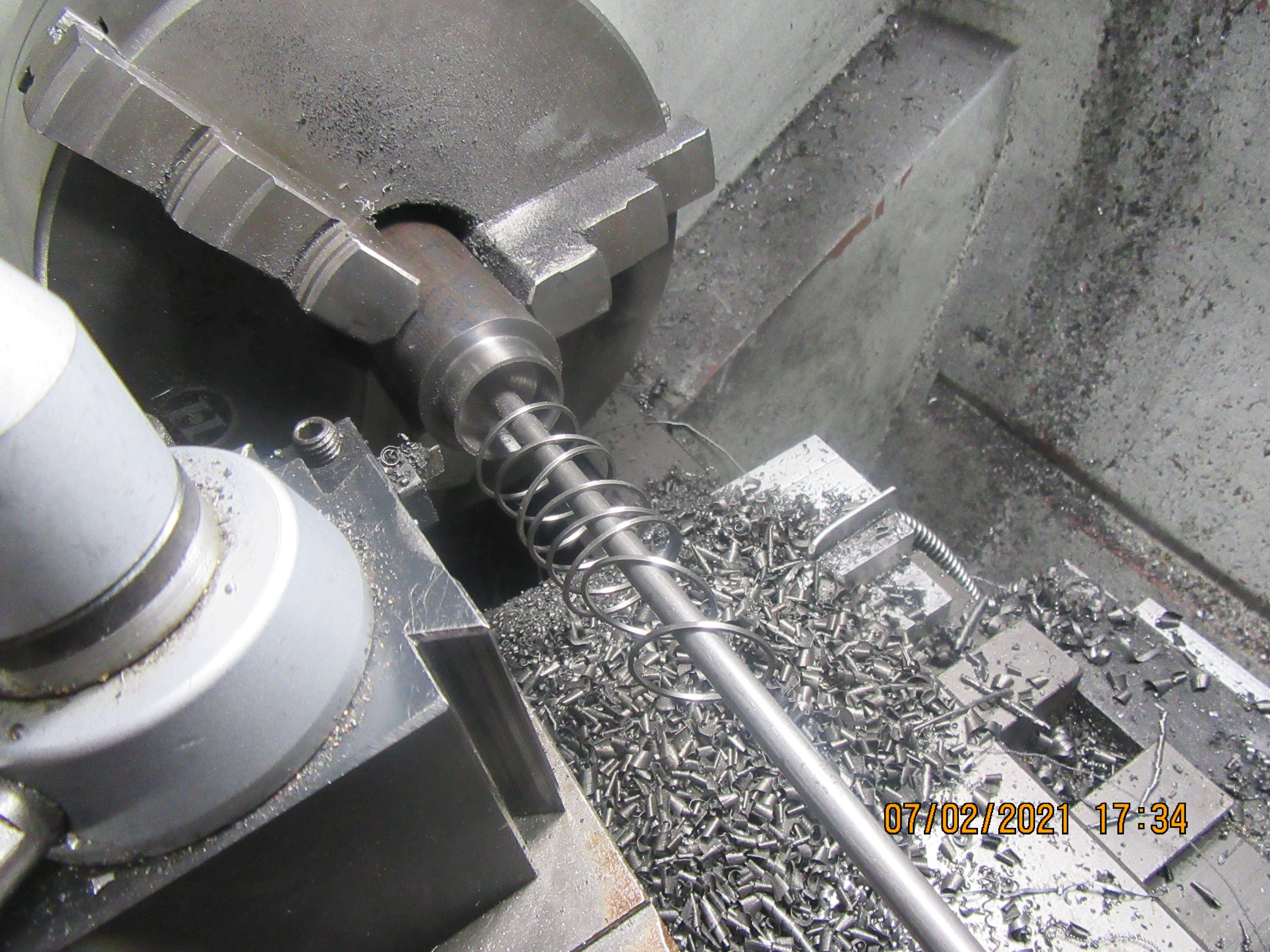
but I'm trying to follow everything that Trimble suggests. Next step will be to mount each ring on the Trimble fixture and deburr/chamfer the side which was not deburred/chamfered before it was cut off from the parent stock. If these rings don't work, there is enough turned material on the "parent stock" to make new rings 0.045" thick, same as Trimble did.

There is nothing like the smell of freshly parted piston rings in the morning.........
A beautiful sight for sure.
.
A beautiful sight for sure.
.
Brian, I don't use a file, I use a piece of alloy flat bar 1" wide and 3/8" thick to hold the emery paper, files have bumps on them the alloy flat bar does not.
Cheers
Andrew
Cheers
Andrew
The rings have been sanded on both sides with 600 grit paper on a flat cast iron surface plate to 0.038" thick, and tried for fit into the grooves on the piston. This picture is the Trimble deburring fixture that "sorta kinda" works. Ring is placed on end of fixture in a "step" machined in the end of the fixture and then the cone is pulled in by the bolt to expand the fixture and hold the ring for deburring. I don't think I would dare to use a cutting tool on the ring because I'm sure it would fly off. However, it does seem to hold the ring secure enough that I can get in there with a piece of 240 grit emery paper and knock off any burrs, both on the o.d. and the i.d. of the exposed side of the ring.
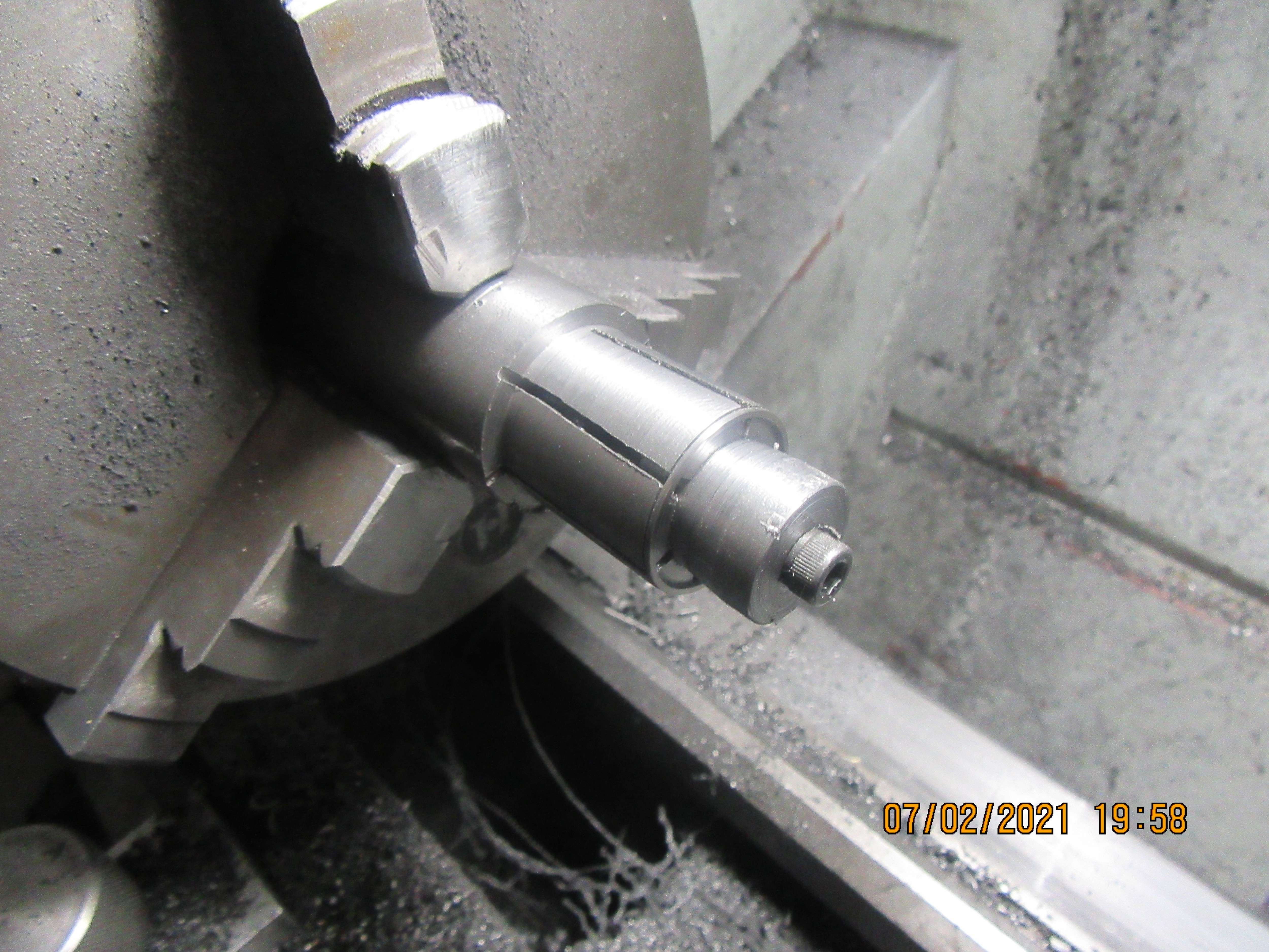

Similar threads
- Replies
- 12
- Views
- 2K
- Replies
- 5
- Views
- 2K
- Replies
- 0
- Views
- 823


