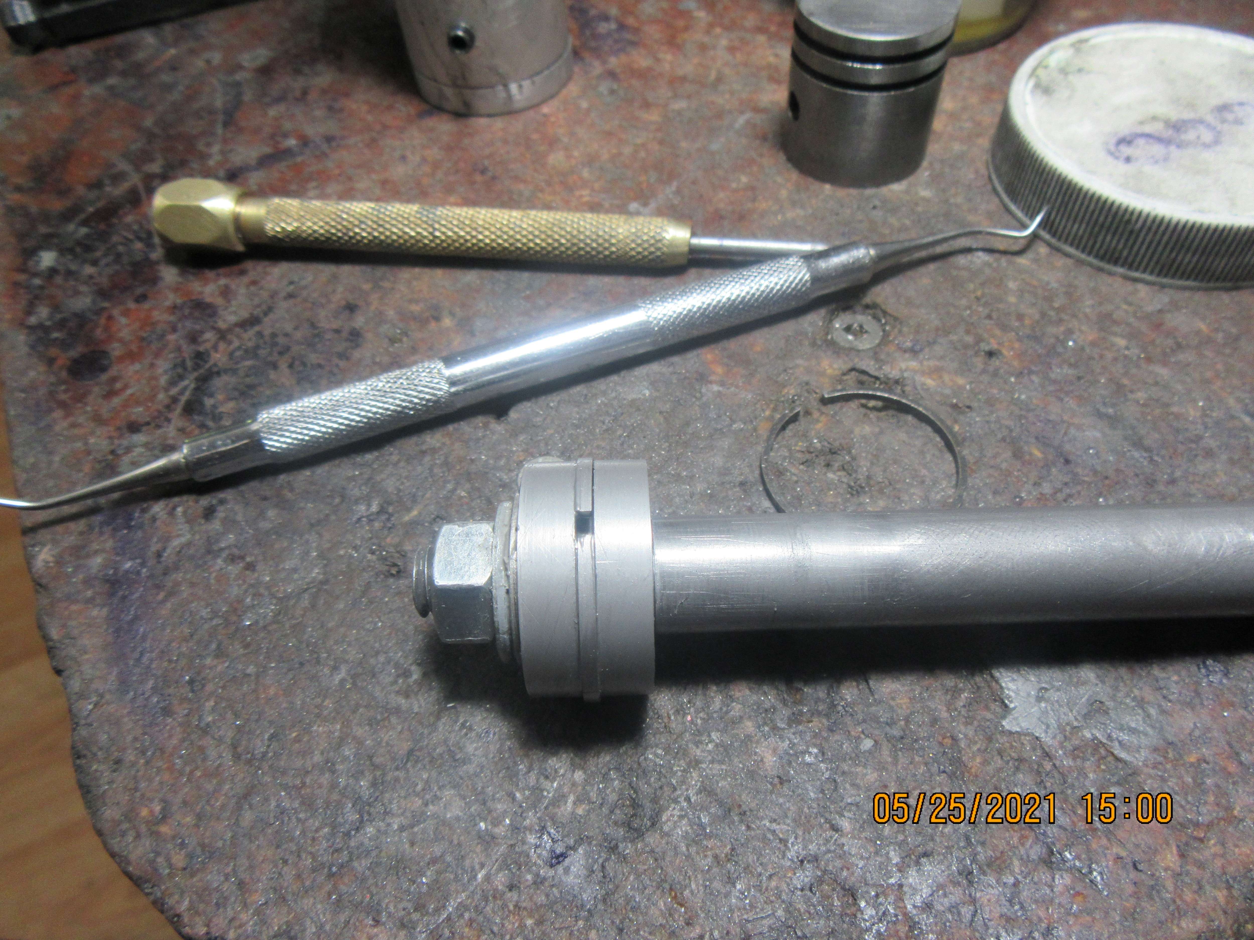
A new attempt at making piston rings

Home Model Engine Machinist Forum

Help Support Home Model Engine Machinist Forum:

This site may earn a commission from merchant affiliate links, including eBay, Amazon, and others.
Nothing is as simple as it seems. The only reason the piston was pushing or sucking on my thumb was because of the oil I had squirted down the sparkplug hole on an earlier test. So, the rings aren't sealing after all. I made a new head gasket, but that's not really where the problem lies. I have pulled the cylinder off and measured it with telescoping gauges and a micrometer, and the top bore taken two places at 90 degrees measures 1.003" and one at 1.004". The bottom measurement taken at two places at 90 degrees apart is the same. I am going to stick my neck out and say that a difference of 0.001" means that the cylinder has not "worn oval shaped". the inside of the cylinder looks fine when held up to a light. After I eat some lunch, I will pull the piston off the con rod and see what wear patterns are on the rings.
Brian,
A thousandth is the limit of the measuring capability of a snap gage. You really need a dial bore gage for these measurements, and a cheap imported one is good enough. But, if your measurements are correct and you haven't made a typo in your post, you've found your problem. Your 1" commercial rings are designed to work in a 1.000" bore and not in a 1.003" bore and certainly not in one that in addition is out of round by another whopping thousandth. Your Debolt rings are showing uneven wear patterns because they expanded to an out-of-round condition because your cylinder is much too large. When talking about cast iron piston rings you need to be thinking in tenths and not in thousandths. Also, if the pistons don't show compression immediately upon assembly, no amount of 'running them in' is going to fix the problem, and you risk damaging the cylinder and/or the rings.

When I machine rings, my biggest problem is turning the ring blanks with the proper i.d.'s and near perfect circularity. Less than half the material remains stable and within a couple tenths for days after being machined and before the rings are parted off. In my experience, three tenths out of round will cause a ring to fail my light test and are discarded.
As far as cylinders are concerned, mine are typically steel, fairly beefy, and once lapped are within a tenth and stable over time. Since your lapped cylinder is so far out of round, it may be a measurement problem. - Terry
 
Last edited:
This is the first ring after 20 full "strokes" of the fixture using 400 grit compound with the lathe turning at 60 rpm and 20 full strokes with the lathe running a 60 rpm with 600 grit paste. All of the wear surfaces on the o.d. of the ring have taken on a uniform color and wear appearance.
mzj7Dc.jpg
 
Terry---Really??? I'm getting lost in this stuff. I have always used Viton rings, and they are very forgiving of bore diameters. I'm doing my best here to come up with a workable solution to making my own cast iron rings, but I'm not having any luck. It's easy enough for me to make a new cylinder with an exact 1.000" bore. I never thought that a difference of .002 or .003" of cylinder diameter would have such a negative effect on the way the cast iron rings work. I'm running out of tricks and I'm still unable to get an engine to run using rings purchased from Debolt. I'm not going to badmouth Debolt rings, because I have used them on a couple of other engines and they worked fine. I'm doing something wrong and I don't know what. Any help you can give me would certainly be appreciated. No one else in this part of Ontario builds small engines, so when things don't go well for me, I have no one I can ask about it.---Brian Rupnow
 
Last edited:
Terry---Really??? I'm getting lost in this stuff. I have always used Viton rings, and they are very forgiving of bore diameters. I'm doing my best here to come up with a workable solution to making my own cast iron rings, but I'm not having any luck. It's easy enough for me to make a new cylinder with an exact 1.000" bore. I never thought that a difference of .002 or .003" of cylinder diameter would have such a negative effect on the way the cast iron rings work. I'm running out of tricks and I'm still unable to get an engine to run using rings purchased from Debolt. I'm not going to badmouth Debolt rings, because I have used them on a couple of other engines and they worked fine. I'm doing something wrong and I don't know what. Any help you can give me would certainly be appreciated. No one else in this part of Ontario builds small engines, so when things don't go well for me, I have no one I can ask about it.---Brian Rupnow
My first suggestion is to make a new cylinder that is lapped exactly 1.000" in diameter and use your Debolt rings that haven't yet been modified. I'd also invest in an import dial bore gage so you can be sure of your cylinder's i.d. and circularity.

If you've already modified them in any way, then I'd consider them scrap and a lesson learned. Then I suggest you follow the time and science proven Trimble method to make your own and make no changes to his process or his fixture. You won't need the toolpost grinder but the oven will allow you to properly heat treat them. When turning blanks for the rings make sure to mike them in two orthogonal directions to be sure they're round to within a tenth or two. Don't be surprised if only a small portion of the blank will pass this circularity test. Allow the blanks to rest a few days before parting in order to verify they're still circular. After parting, follow the Trimble process. Make a light test fixture using a high intensity led flashlight and, before installing the rings, make sure they pass the light test in a dark room. Don't be surprised if a few more end up discarded.

I find it easier to make my rings match my cylinders which always end up a thou or two oversize because I build multi-cylinder engines and lapping 4 or 12 cylinders to exactly the same size usually doesn't allow me to hit a specific diameter target. So, every engine I build winds up needing its batch of rings, and I end up with plenty of leftovers that will never be used in another engine. In your case, most of your engines are single or two cylinders and usually the same diameter. If you can really hit your 1.000" bores, then you can make a lifetime batch of rings in one setting with little more effort than needed to do a couple for just one engine.

You can look back on my builds for the Offy, Knucklehead, Merlin or any of the radials. I went into a lot if detail on my ring making process including the issues with getting good ring blanks. Since I too was learning along the way, my last build, the Offy, is probably my best reference.

Don't run the rings in with an external power source. If you don't have compression, disassemble the engine and figure out why. If the rings are at fault (most likely they're not if you followed the above) you stand the chance if damaging the cylinder wall.

That's my two cents
Terry
Can you give us a brief rundown on the process and steps you use in boring a cylinder and holding it round within .0005. That is a degree of precision I have never attained but like Brian I do not have nearby experts but I am willing to learn.
 
Can you give us a brief rundown on the process and steps you use in boring a cylinder and holding it round within .0005. That is a degree of precision I have never attained but like Brian I do not have nearby experts but I am willing to learn.
I lap the last couple thousandths with a barrel lap. - Terry
 
Can you give us a brief rundown on the process and steps you use in boring a cylinder and holding it round within .0005. That is a degree of precision I have never attained but like Brian I do not have nearby experts but I am willing to learn.
With care you can get a bore within 0.001" of the target diameter using only the boring bar, no lapping required. But that's not a big deal on a single cylinder, you just get within 0.005" and make the piston and rings to match. Boring bars naturally cut a true circular bore (taper is another matter, make sure your lathe is in good condition and well aligned) subject to the circularity of your headstock bearings. My lathe uses wheel bearings from a truck, which should have at most 0.0002" deviation from circularity. Far better than I can measure.
 
Boring bars naturally cut a true circular bore (taper is another matter, make sure your lathe is in good condition and well aligned) subject to the circularity of your headstock bearings. My lathe uses wheel bearings from a truck, which should have at most 0.0002" deviation from circularity.

I'm not 'into piston rings etc' but I've successfully bored the parallel 1" bores that form the base bars of the Quorn tool and cutter grinder. Theoretically there are THREE sets and are 3.5" apart.

There are TWO in line boring bars and provided the lathe is true, there is no question that ALL three bores will be of equal size and truly parallel. If the tail stock is 'out'. the bores wull ALL be oversize but will still remain truly parallel and concentric to one another.

The priciple is explained in Geo Thomas's Model Engineer's Workshop Manual.

He asserted that he could finish his boring to a greater finish that could be obtained by using reamers etc.
The book was written to suggest that today's carbide tools and the then high speed steel actally produced inferior finish to that produced using the age old carbon steel tooling properly tempered and honed.

Worth a read- my opinion of course

Norman
 
All and I mean all rings need to bed in it’s a fact ! But I’m following with interest Brian the right oil can be the secret? Maybe I’m learning too of course but you do need a break in oil that I’m shore .
 
Much like the final linishing and barrelling rig I saw in the H & G ring factory. At the end of each return stroke, the cylinder was roared something like 20 or 30 degrees.... it was mounted on a pivoting frame - like an oscillating engine - and the linear motion generated by a crank, as in the real engine. The idea being that the changing forces from the crank would simiulate the tiny oscillation of the piston rotating on the gudgeon pin (piston-pin for the West Atlantic tribe). The tiny oscillation forces "barrel" the surface of the rings, so the "spherical linishing" ensures a full line contact of the ring as the piston oscillates. Otherwise this needs a running-in to develop naturally in the engine. Steel wire rings are formed using die rollers that imbibe the shape to the outside surface of the ring without the need for the "barrelling" process. I think in the USA there is a company "Perfect Circle" who make steel wire piston rings?
Well done Richard for finding the ovality in the bore.
K2
 
Tim, the Running-in oil is generally very rich in detergents, to aid cleaning and clearing microscopic swarf from the bearing surfaces,
It still has good lubricity, like any other lubricant, but has a lower shear strength, so is the opposite of EP Gear oil (EP = extreme pressure). The "LP" sort of grade permits the microscopic contacts of running-in that knock-off high spots a bit easier than normal oil would permit by a break-down of the oil film. It should be replaced with proper lubricating oil after a relatively short running-in period.
Never use Molybdenum during running-in. This excellent anti-scuffing compound should be used to slow further wear after the first normal oil change period, not before.
Hope this helps?
K2
 
Nothing is as simple as it seems. The only reason the piston was pushing or sucking on my thumb was because of the oil I had squirted down the sparkplug hole on an earlier test. So, the rings aren't sealing after all. I made a new head gasket, but that's not really where the problem lies. I have pulled the cylinder off and measured it with telescoping gauges and a micrometer, and the top bore taken two places at 90 degrees measures 1.003" and one at 1.004". The bottom measurement taken at two places at 90 degrees apart is the same. I am going to stick my neck out and say that a difference of 0.001" means that the cylinder has not "worn oval shaped". the inside of the cylinder looks fine when held up to a light. After I eat some lunch, I will pull the piston off the con rod and see what wear patterns are on the rings.
Brian
I can't tell form the material list. What is the honing jig cly made of? If its not hard during the honing which will wear in the cly or the ring?
Harvey
 
Before, I wasn't sure if my cylinder was good enough , so I made a ringless piston and used it, if the engine runs well then my cylinder is fine, and vice versa the cylinder is not good enough
just my thoughts, if the engine runs well with a ringless piston it will eliminate other possible causes of the cylinder: whatever shape
Anyway making a round piston is not too difficult and it is much faster than making a new cylinder
And one more thing worth paying attention to: the bottom surface of the groove, it contributes to sealing .
 
This is the first ring after 20 full "strokes" of the fixture using 400 grit compound with the lathe turning at 60 rpm and 20 full strokes with the lathe running a 60 rpm with 600 grit paste. All of the wear surfaces on the o.d. of the ring have taken on a uniform color and wear appearance.
mzj7Dc.jpg
I am confused about this fixture. The drawing says the ring should float between the two discs. Then you say that you ran the lathe at 60 RPM. If the rings are not retained in the fixture they are going to turn with the outer sleeve and just wear the sides of the rings. The rings are going to be no better than the outer sleeve ID and once you start moving the sleeve is going to wear and soon be oversize. If it is just moving laterally it is no different than putting the rings on the piston and moving it back an forth in the engine cylinder.
 
Mayhugh1-You said that you make your cylinders out of steel. What material do you make your rings and pistons from? Hot rolled steel is about 1/4 the price of cast iron, but I have never used it for a cylinder. I have always used cast iron, but would gladly change to hot rolled steel is it does a good job and there are no unusual friction or wear problems.---Brian Rupnow
 
Gordon--I don't know if the rings turn inside the fixture during lapping or not. I never used this tool before. I only made it two days ago. I'm thinking it probably does turn a bit, based on the beautiful matt finish on the rings o.d. after the lapping tool is used.----Brian
 
I must admit to being totally flummoxed. Lapping the o.d. of the rings with my newly made tool has given a beautiful finish to the outside diameter of the rings. They STILL don't seal in the cylinder. The i.d. of the cylinder looks perfect. The rings look perfect. The piston was made deliberately 0.002" smaller in diameter than the nominal 1.000" cylinder bore. The cylinder actually mikes at 1.003" to 1.004" inside diameter. In a worst case scenario, the piston may be 0.005" smaller than the cylinder bore. I could deliberately make a new piston that was lapped into the bore and needed no rings at all, but this entire exercise is about successfully making rings. I truly am at the point where I don't know what to do next.----Brian
 
I mentioned a way of checking for out of roundness. A very simple way is take your cylinder put it in afour jaw chuck on the lathe. Clamp it only enough to hold it your not machining it only using lathe as a gauging device. Now try dialing the bore in with a dial indicator it will show you out of roundness but remember lightly clamp just to hold cylinder. If you can dial it in then all is good if not it will show how far you are away from being perfect. Snap gauges are only as good as your feel and takes a lot of practice and what brand snap gauges you have. Plus a snap gauge will measure a bore dia bigger than it really is (for me) usually about .0002-.0005 bigger than it really is on a 1 inch bore. The larger the bore is the more the measurement will be off also.
 
Hi Brian, this is just an idea - not proven - but when I was an apprentice, I was taught that the Delapena Hone we had - that I used for con-rod small end bearings - could only make a round hole, not elliptical or multi-faceted. Therefore I would suggest a "rigid" hone. The Delapena machine could turn on 10ths of thou cut form the stone, as it had mandrels of many sizes and used a tapered shaft to expand the stones. So it could not make an ellipse or other shape, which spring-loaded stones would do.
Use of a reamer, or so I was taught, would make a multi-faceted hole, with the number of facets equal to the number of cutting edges plus 1. Although I can't recall anyone else ever saying this, I believe it is true "mathematically". So don't use a reamer.
Having eliminated spring loaded hones, and reamers, you have broaching (who has a broach when you need one?), or "proper" honing with a "rigid" set stone arrangement. Is it possible that the cylinder was squeezed when clamped for boring? Or maybe it got hot and was distorted when bored? (Therefore out-of-true when cooled?).
What is the hardest wood (or aluminium?) you have in 1" diameter? Machine a slot and insert a fine stone slip (1/4" square or smaller? - maybe 3/16"?). Shim it to be EXACTLY the size you want (1.0032"?)and use as a hone - then shim with another *** paper (or the foil from the inside of the *** packet?) and repeat - until you get to the 1.004" you require? Remember it will be "grinding" on the corners, not the flat face. The hone should be between centres, with the cylinder worked axially to give the diamond cross hatch.
But I am sure you know this - or did it already? - But someone else may not have tried this.
Regards,
K2
 
Hi doc1955: I didn't know bore gauges gave larger bores than measured... I thought they had small radius ball ends to accommodate the bore curvature? - Or maybe I misunderstood your info? - I use inside callipers myself, although I bought some "spring-loaded lockable" bore gauges, I still just use the inside callipers.... set to the bore, then compared to a mic. - Never had a problem that I know about.
Cheers.
K2
 

Latest posts

Back
Top