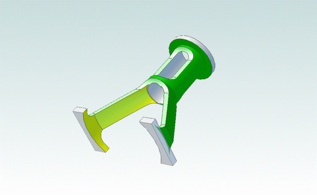
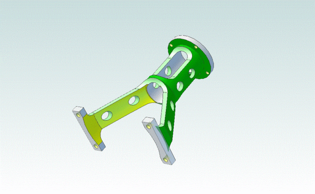
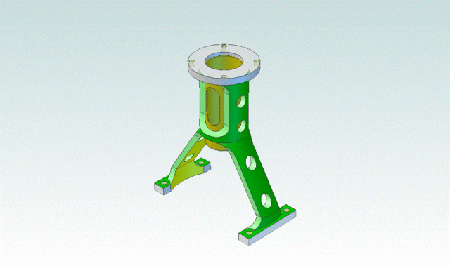
A diversion.

Home Model Engine Machinist Forum

Help Support Home Model Engine Machinist Forum:

This site may earn a commission from merchant affiliate links, including eBay, Amazon, and others.

Captain Jerry

Project of the Month Winner!!!
Project of the Month Winner
Joined
Dec 2, 2008
Messages
971
Reaction score
9
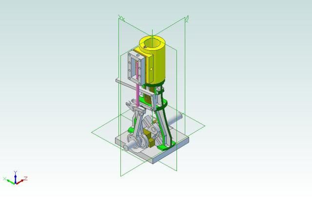
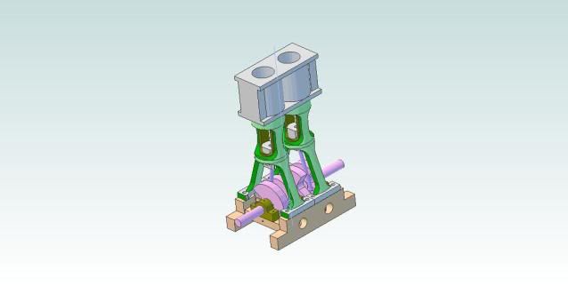
I'm going to post this here because I don't know where else to put it. It's not really a work in progress. The design is not really finalized, and I already have a major work in progress, and that is the problem. Unlike a lot of you, I don't have a job to divert my attention, my boating days are almost over, and my dog went to college with my granddaughter. I have almost unlimited shop time, but there are times that I just want to fool around in the shop and NOT work on the donkey. I do not mean to abandon the donkey, just do something else once in a while when the donkey goes stale.

The donkey engine build may go on for a years and in the meantime, there are some other things I would like to achieve. For example.

A multi journal crankshaft, either built-up or one piece.

A reversing engine, either Hackworth or Stephenon linkage.

A trunk type crosshead mechanism.

An engine built with castings.

I see all of these really cool things on this forum and I want to get in on it. Here's what I'm thinking:

http://screencast.com/t/NFSz0huLchTI

At this point it is an Idea in Progress.

Jerry
 
Oops,

I was trying to post and animated video but I didn't get it right. Here are some stills:

VerticalEngineREVB.jpg


or this:

Geometrybased.jpg


Jerry
 
Crikey,

That's a diversion :eek: :eek:

I may have a diversion of my own, tomorrow I am going to see about a job of 10 small precision parts to be made. Wish me luck.

Best Regards
Bob
 
Good luck, Bob.

Really!

Jerry
 
Hi Jerry, I hear what you are saying and I also take time out from my major work to do 'other stuff', its a break from the one thing and I see no problem with it....

It ssounds liek you feel guilty about it... ;D if so, mate, dont....... its a hobby and we are supposed to enjoy it... at our pace.

Cheers, looks great.....

Rob
 
This has not yet become a "project" so I guess this is the proper place to show the progress. My shop time has been severely limited lately due to travel and boat work so my machining is mostly limited to 3D cad. I have said before that I was not very successful with 3D until I approached it from a part making point of view, starting from solid and removing metal just as on the lathe or mill. This made 3D modeling work for me and has the advantage of developing the machining sequence as well.

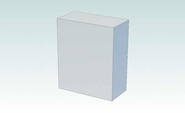
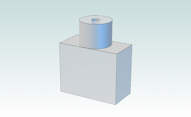
The following sequence (.GIF files exported from Alibre') I'll show you what I mean. It starts out as a block of aliminum 2" wide, 1 " thick and 3" long.

AltframeDbowedstage1.gif


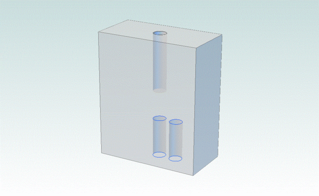
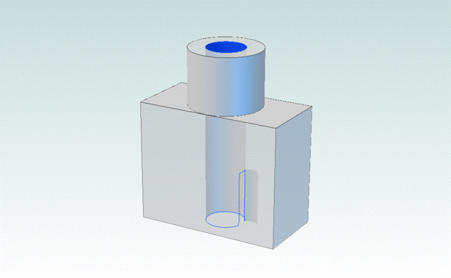
Holes are drilled top and bottom to mount in the lathe. Centered on the top and bottom faces are 1/4" holes for live center and dead center, and an offset hole for a drive dog. The position of the drive dog hole is not critical as it will be machined away later.

AltframeDbowedstage2.gif


Mount in the lathe between centers and turn to 1" diameter for 1.5" from tailstock end.

AltframeDbowedstage3.gif


Remove and reverse in the lathe, gripping the cylindrical end in the 3-Jaw. Mount 1/2" bit in tailstock and drill clear through.

AltframeDbowedstage4.gif


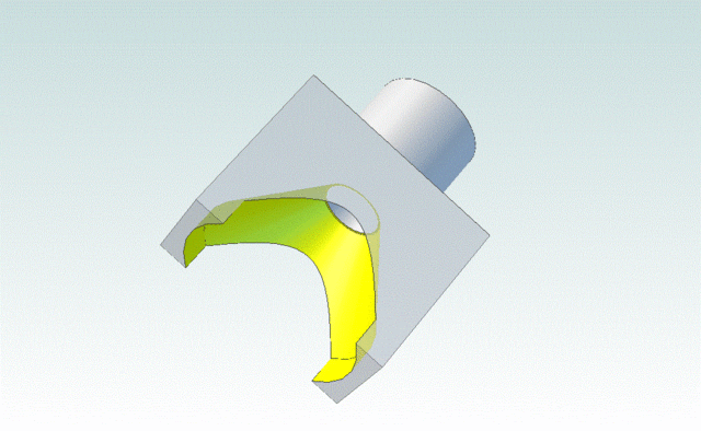
With the compound set to 30 degrees, bore the inside conical face. This step will be a lot of fun, a nearly blind internal bore with an interrupted cut! Note the straight cylindrical entrance before the start of the conical section.

AltframeDbowedstage5.gif


The part is removed from the chuck and mounted on a mandrel for the next step. The outer conical section is turned with the compound still set to 30 degrees and the top cylinder is reduced to .75" except for the top 1/8 inch left for a mounting flange.

AltframeDbowedstage6.gif


The part is then clamped to an angle plate on the mill table and the faces milled as shown. Reversed on the plate and the opposite faces milled.

AltframeDbowedstage7.gif


Mounting holes are then drilled in the feet and the upper flange. Holes are also drilled in the legs and trunk for visual appeal.

AltframeDbowedstage10.gif


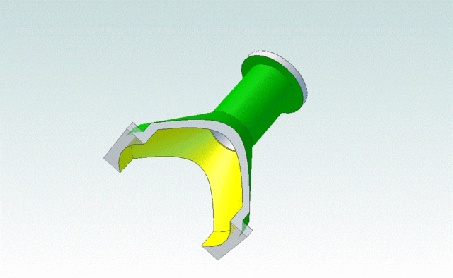
The final step is to insert a brass liner in the trunk guide.

AltframeDbowedwithguideinsert.gif


Actual dimensions are not shown. This is meant to show the developement steps. It also points out a great benefit of 3D modeling. That is the accurate depiction of the intersection of curved faces and complex shapes.

This may turn into a real project soon.

Thanks for tuning in.

Jerry
 
Pat

I was interrupted during posting so it was incomplete before. It has been edited. The GIF's are not animated.

Jerry
 
Pat J

Thanks for the compliment but I have a long way to go to claim 3D mastery. I am comfortable with the tools that I use but I frequently find better ways to use them and there are many tools that I haven't even attempted to use. For a while, I would revert back to 2D for simple sketches, but I don't do that any more. It took a while but I learned to stop thinking in terms of lines and more in terms of geometric solids.

Keep at it. You will get it. You younger guys pick up new stuff easier than us dinosaurs.

Jerry
 
Jerry...
good to know I'm not the only one who gets project burn out. The current VW project was my way to escape from the shop, for a bit and it's filled the time void nicely until I'm ready to attack the small stuff again. Taking a break from a complex project is a good idea, now and again.

Steve
 
Hm. Very nice GIFs, but are you sure the holes in the legs would be a good idea? This type of legs are usually ribbed, trying to make them stronger against bending loads. Holes in them would have exactly the opposite effect. I suppose the legs would support the loads present in this engine, but to me, they would not seem right ;D


fab1_glissiere.gif


Stuart_No_10_Engine.jpg
 
Jerry--Kudos to you for the 3D cadwork. I know how much pain goes into the learning curve of making comprehensive models. Congratulations sir!!!----Brian
 
Jerry,
Thank you for your demonstration, I to have been plodding along with Alibre on a vary steep learning curve. The start with a block of steel and machine away in 3d in a methodical machining way is certainly a help to me. I took Autosketch off my computer so there was no going back to 2d.

Thanks again, Lance
 
Steve

Maybe it's burnout. Or maybe it's impatience. I have seen many fantastic models that are obviously lifelong projects and while the donkey might be a lifelong project. I seem to have been hit with a large dose of impatience so maybe a project with a lower part count might help me get over the self induced pressure to complete something. I don't work very fast, partly because of minimal tooling but more likely due to minimal experience.

CIDROMTMG

Thanks for your comments. You may be right about the strength of the legs in this model. I'm not an engineer and this is not a model of a real engine. The Stuart engine that you showed is obviously an inspiration for this design and is a great model relying on grey iron castings. I don't have a foundry at my disposal but I do have a lathe. You also show a welded plate fabrication which is another way to construct this style of engine but I don't have those skills either. Aluminum may not be appropriate for construction of full scale engine but should be more than adequate for this model. A CNC mill might be able to produce a copy of the ribbed structure of a Stuart casting but I don't have one and that was not the object of this exercise any way. The object was to design a one piece structure from aluminum with modest tooling and little experience.

In spite of all those qualifiers, I think the strength of this design may be very close to the ribbed design of the Stuart casting (if done in cast iron). Because the width of the leg is greater than the Stuart design the cross sectional area may be equal or greater. The rib does add stiffness and there was a recent thread that discussed the stiffness of various shapes, speciifcally comparing I beam or H beam shapes to solid bar but there are other shapes that can be used to add stiffness such as box and angle shapes. The cross section of these legs is a shallow C shape that adds some stiffness.

Another factor to consider is that in many structural shapes, material can be removed from the web portion of the beam for weight reduction without greatly reducing the stiffness. I'm not sure that the holes in these legs qualify in that regard but maybe. There are people on this forum that have the education to make that kind of analysis. If any of those people are watching, please comment. I'm not an engineer, I just pretend to be one in my little shop.

Brian

Thanks for the comments. As we all know, when it comes to 3D modeling, "You da man!"

Jerry
 

Latest posts

Back
Top