A different engine configuration

Home Model Engine Machinist Forum

Help Support Home Model Engine Machinist Forum:

This site may earn a commission from merchant affiliate links, including eBay, Amazon, and others.

Brian Rupnow

Design Engineer
Project of the Month Winner
Joined
May 23, 2008
Messages
15,250
Reaction score
8,532
Location
Barrie, Ontario, Canada
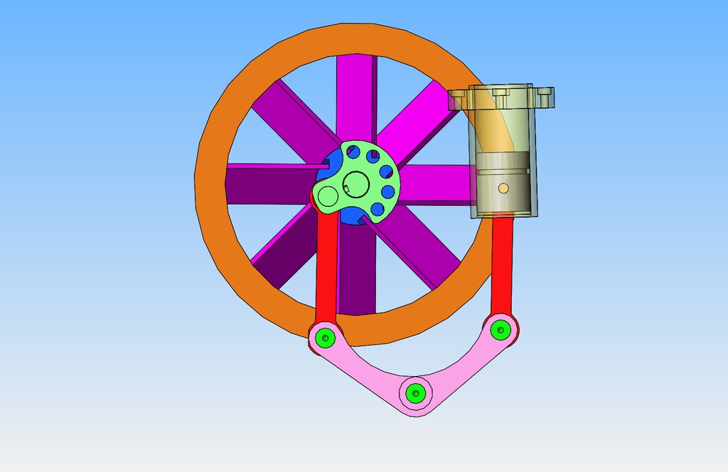
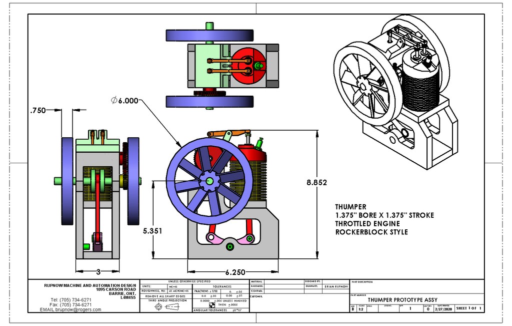
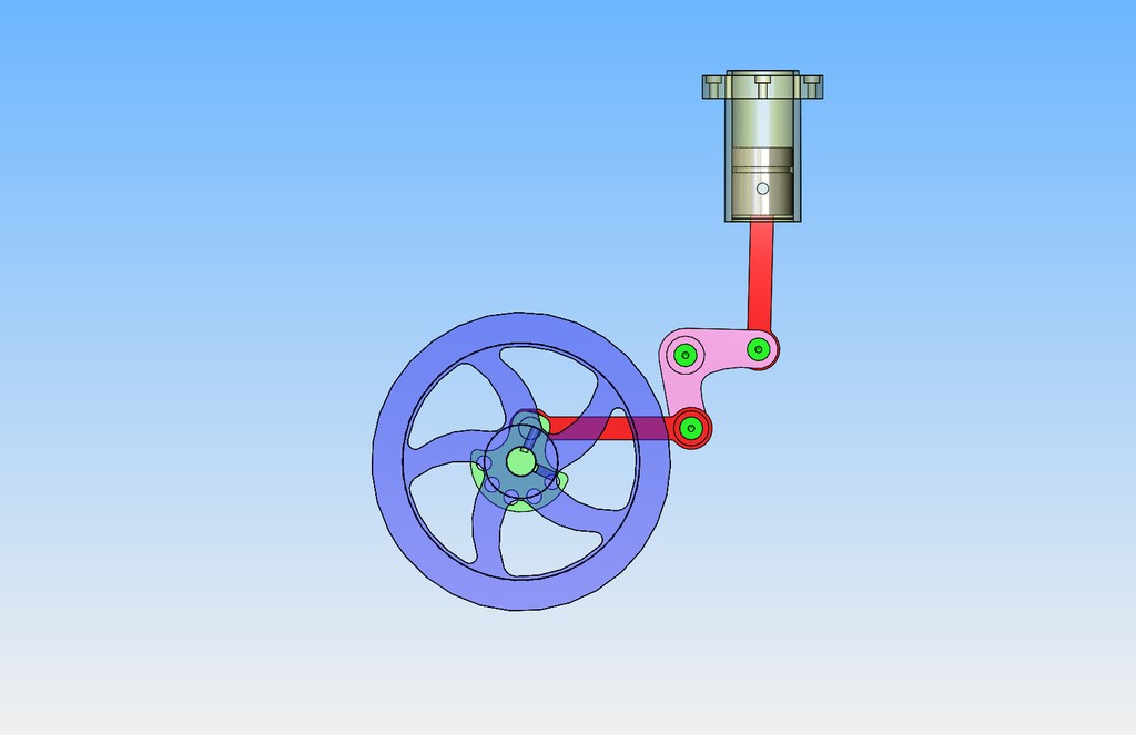
Has anyone seen an i.c. engine which operates with the crankshaft being driven by a "Bell Crank"? The closest I have seen to this is the Rockerblock engine which I designed and built a few years ago. I'm casting about looking for a new engine to design and build, and I don't remember seeing this configuration before.---Brian
zbZeXi.jpg
 
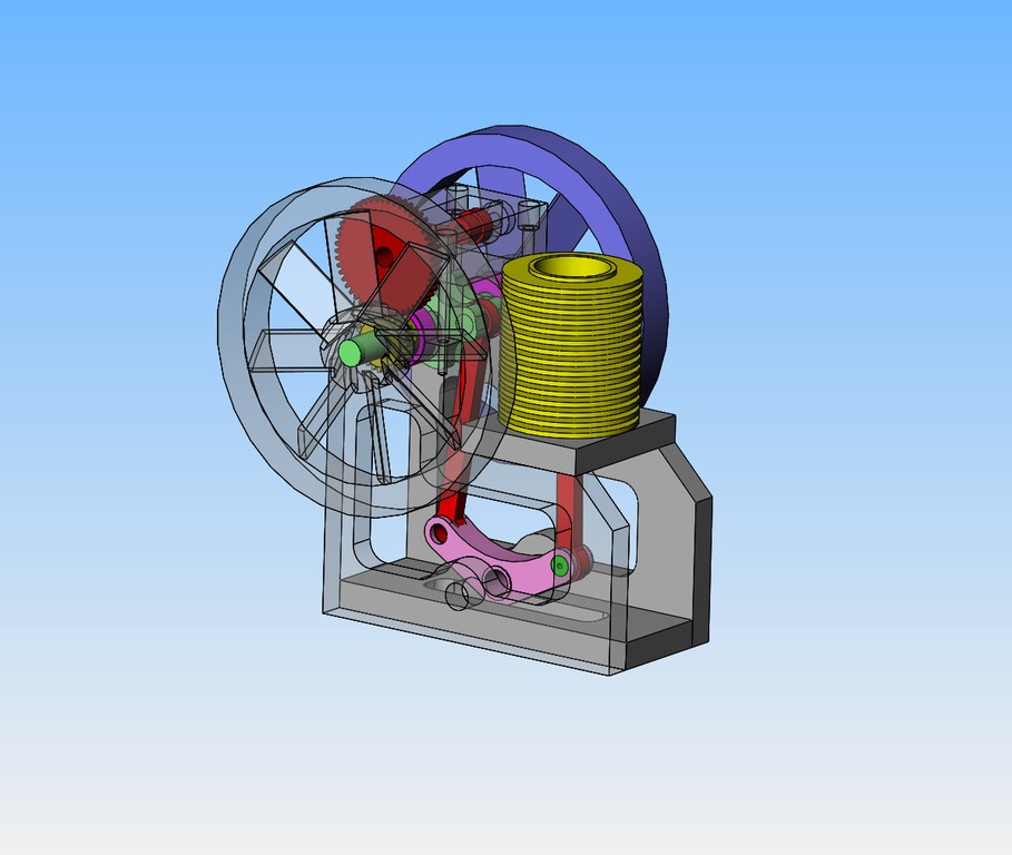
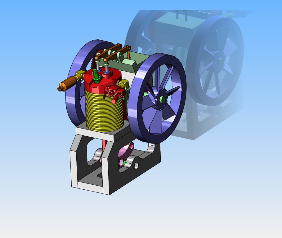
I have a few new things going on. Biggest new thing is that I just bought a tig welder. A tig welder will let me fabricate vaned flywheels. If I take the Rockerblock concept and rotate it until the cylinder sets vertically, then I can almost fit an air cooled cylinder directly in the flow of air from the vaned flywheel.
obmBew.jpg
 
There are Stirling engine configurations that depend on bell crank components. You can take a look/see for inspiration. My best guess though for a gas engine is that inertia and balancing issues would jack hammer a prototype engine all around the table. Is that a concern when changing direction vertical to horizontal or down to up of a power stroke using a bell crank?
 
Hi Brian, Great project!
The basic design is around 130 years old. Below is a video of an 1891 4 hp Van Duzen inverted walking beam engine
along with a new re-design that a fellow in China is working on which is a horizontal version of similar design.

Gil


M100.JPG
 
Red Ryder--The 3D engin e on the bottom is the Rockerblock engine which I designed. If someone in china is building it they have stolen my design.---Brian rupnow
 
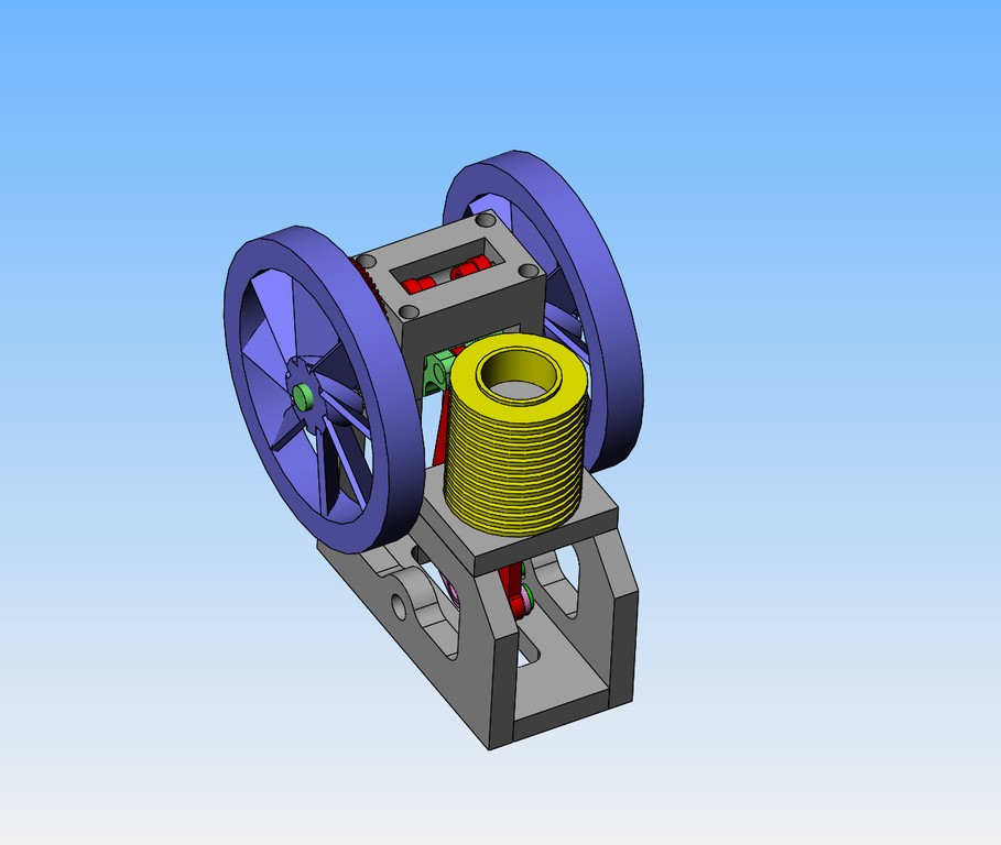
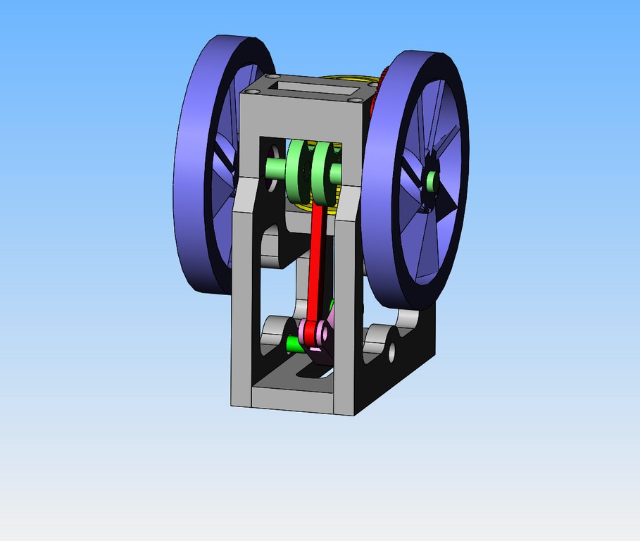
Well, I'm pretty excited about how this is turning out. Everything seems to fall into place without any major problems. I have to add in the carburetor and exhaust yet, but this makes a surprisingly small package for an engine with this displacement which is 2 cubic inches.
WBiH6X.jpg
 
I managed to get the intake and exhaust all in place, although I thought I might have to make the flywheels a bit smaller in diameter that I had planned. It turned that everything fitted into place without changing the flywheels.
TVoSSB.jpg
 
I am going to end this thread off at this point, and begin a new thread dealing with the fabrication of the engine under the heading of "Thumper--A new 1 3/8" bore i.c. engine"
 
Brian or any others,

As I have pondered your new design (and thought back on the horizontal RockerBlock design), I got to wondering whether there would be any advantages or disadvantages if one moved the pivot point of the rocker lever. In the current design(s), the pivot point is centered, so the ratio of movement of the piston rod to the movement of the rod connecting to the flywheel is 1:1. But if you moved the pivot point, you could change that ratio to, say, 2:3 ... or 3:2 ... or so on. Would there be any potential advantages in doing this? Disadvantages? Or would it make not the slightest difference?
 
Look at post #12--this thread is finished. I have an engine here with a rocker on which the pivot is not centered. It gives some very unusual movement of the piston because the forces differ so much as a result of the hole not being on center.
 
Commer Knocker engine in NZ
These engines were produced by the Rootes Group of which Commer was an automotive division. A marinised version was marketed by Lister Blackstone as the Rootes-Lister TS3. I managed several tugboats with these installed as the prime movers for alternator (generator) sets running at 1200RPM for a 60hz supply. Apart from being very noisy they were ultra reliable; they were often stripped for Lloyds surveys and found with pistons worn as much 0.25" undersize despite operating trouble free at full output!
 

Latest posts

Back
Top