3D print a conrod pattern

Home Model Engine Machinist Forum

Help Support Home Model Engine Machinist Forum:

This site may earn a commission from merchant affiliate links, including eBay, Amazon, and others.

lee webster

Well-Known Member
Joined
Oct 4, 2019
Messages
323
Reaction score
118
Location
Cornwall UK
I am nearly ready to try a casting using patterns made with my resin 3D printer.
IMAG0001_1.jpg
IMG_2068_1.jpg
IMG_2071_1.jpg

I printed the conrod pattern with my resin printer and the baseplate with my Ender3. The baseplate will need the layer lines filled in, but that's a simple task. The plate has two raised bosses that the conrod sits on. The conrod will be glued onto the plate and any minor impefections filled. I will make a frame that fits around the plate to create a mould for either resin bound sand or maybe sodium silicate bound sand. I might try both. I still have to work out how to create a way in for the molten aluminium. The hole in the little and big ends are 6mm dia, the conrod is 89mm long, I forgot to include a rule for scale. The first picture shows a different conrod alongside the one I will cast.
 
I've seen people print the gating pattern and glue that to the match-plate. I think it was Myfordboy that I saw do that?

If you are gong to use some type of bonded sand, it sounds like you don't plan on using a flask. Will you be making something that will key the two parts of the mold back together correctly?

It looks like there's an open space where the 6mm holes are, between the match-plate and the pattern. Will you be filling this with something? If you don't, won't this allow the sand to key into this area, and not allow the sand to release the pattern?

Don
 
Hi Don.
I am not sure who did the video on glueing the gating to the plate, but it sounds like a good idea.

I would make a flask that was a good fit around the base, the blue bit. If I use the same flask to make the top and the bottom of the mould they two halves should go back together with the conrod matching, I hope.

I made the space between the conrod and base on the large side to give myself a bit of wiggle room. I will make a sprue and riser to fit in the two 6mm holes. I will pour at the big end and let it rise at the little end. That is the plan. I had a bit of a setback today when after I glued the two parts together, and filled those gaps!, I gave it a coat of paint and let it sit for a few hours. When I brought it indoors to sand the paint I discovered that the conrod had distorted on the base. I am not sure how.
IMAG0010.JPG
 
That sucks. The good thing about 3D printers is that it doesn't take much effort to make another copy when things go South on you. You could always print some dimples and bumps in the plates, that way they'd self-align when put together.

It was Myfordboy that I was thinking of, but the pattern wasn't 3D printed. it was laser cut. But that's almost same-same. Here's the link, it might give you some ideas.


Don
 
Last edited:
I am subscribed to Myfordboy and I watched that video when it was released. THanks for the link though, I might watch it again.
I have seperated the conrod pattern from the baseplate and managed to bend it back into shape with a little heat. I have now rebonded the conrod to the plate holding it in place with small clamps. I used a digital caliper to ensure that the conrod was central to the plate. I am wondering if the spray paint expanded the conrod in some way. Really weird.
 
Putting dimples in the plates won't work for the way Lee wants to do the moulding, it's fine for cope and drag but he wants to do a form of shell moulding. In this case you would end up with a dimple facing a dimple so not going to do much to line things up. The plate Lee is proposing to use is not a match plate.

Strange that it only distorted on one side, was there more paint on that side as the solvent could have affected the resin. Is it affected more by cellulose paint than acrylic? Also if left outside was one side facing the sun?
 
This is my first experience with resin printing, so I don't know anything about reactions with paint etc. The big end and little end are hollow to allow them to fit over the bosses in the plate and to save resin. The rod body is slightly hollow, again for resin saving. The paint used was an acrylic primer applied in a garage that has no sunlight. Temperature was about 65 to 70F. I am going to check out Myfordboy's video. I think maybe a match plate is a good idea. It would mean printing two rods, but I wouldn't need to print bases because the rods (solid with the same 6mm holes for location?) could be fixed directly to the match plate. I would use two pieces of melamine, one for each rod half. I haven't used a match plate before, it should be interesting. I would have to make a timber flask to suit.

The other thing I am thinking of doing is to print out two rods, both as hollow as I can make them but the 6mm holes would have a boss that went from face to face, poor explanation I know, then I could fill the hollow part of the rods with an epoxy putty before fixing them to the match plates. The epoxy putty should give the rod some extra strength, maybe even enough for greensand ramming. At least the rod would be more stable.

I do like the idea of a match plate though.

Edit. I didn't mention that I am using two water washable resins for my printing. One from Creality and the other from the company I bought the printer from. I don't know if a standard resin would react any differently. My printing is done in a utility room which is part of the house, so smell was something I had to consider. The utility room is off the kitchen and you can't smell the resin from there even with the door open. I use isopropol alcohol, IPA, to clean the FEP sheet at the bottom of the resin vat after I have washed the vat with water. The IPA ensures that all the resin is cleaned off the FEP. The IPA has a very strong smell that can be smelt from 20 feet away, and I only use a dap on a cleaning cloth. To have a cleaning vat filled with the stuff is a no-no if used indoors.
 
Last edited:
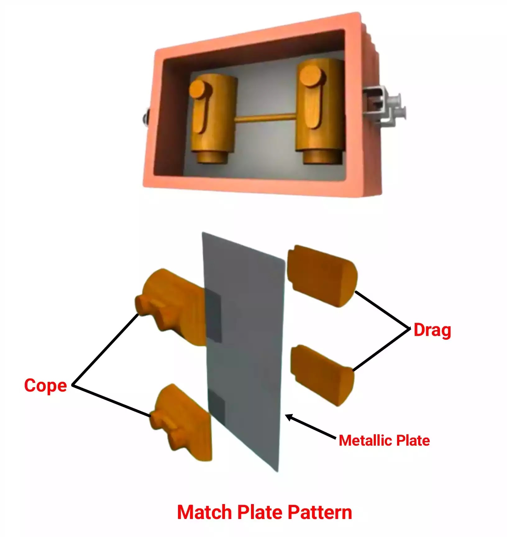
As your part is symmetrical you could get away with a single printed half pattern even with a match plate, can't with that Myfordboy example as it is not symmetrical.

You would need the location pegs like he has, place one half of the pattern onto the matchplate and mould that. Then remove pattern and locate on opposite side of the matchplate and mould that, when the two halves come together you will have a mould just like one done with two half patterns but only half the resin used.

Not sure what you mean by two pieces of melamine, if that is for a matchplate then only one would be needed but make sure location page sate truly vertical through that thickness. You fix one half of the pattern to either side and that is what keeps things linedup, if you use two boards then you need to make sure they stay lined up


type%20of%20pattern%20-%20match%20plate%20pattern.webp
 
Last edited:
JasonB.
My idea was to clamp two pieces of melamine faced furniture board together with a flask clamped on as well, mark out the dowel holes for the pattern and drill through both boards, and at the same time drill through the brackets on the flask too. Your way might be easier and more precise.
I have redesigned the rod by making it a bit thicker and also making it solid but still with the two 6mm holes. This time I won't use a base plate.
 
I separated the conrod from the base plate and cleaned them both up. I then glued the conrod back on the plate and filled any gaps. That was over a day ago and the conrod hasn't distorted. I think the initial distortion was caused by the paint, so I didn't paint it this time. I have 3d printed two sprues and two blanking buttons on the Ender3. The buttons will cover the 6mm holes when I fill the first half of the pattern with sand, resin bound or sodium silicate, not sure yet. When that half is set I will remove it from the pattern and replace the buttons with the sprues. When I get the sand to the top of the flask I can then scrape out some kind of pouring basin in the sand around the sprue located in the big end of the conrod. When that half is set I can remove the sprues and strike the mould. I should then have two halves of a mould in set sand that can be bonded together, I think. When the mould has sat for a while (I do have a small electric oven I could "cook" it in) I can then melt some aluminium and pour. Next step is to make a flask, just one half? and get the flask and conrod in the correct position on a board properly located with pins. If this method works, or rather, if I can do it properly so it works for me, it will make casting certain parts much easier.
 
I started both my Ender3 and Anycubic printing today, more attempts at getting a conrod I can use for casting. The Ender printed OK, a slight mishap I spotted early on where one of the prints was starting to lift from the bed. Because the nozzle was working on the other print I used some celotape to stick the offending side down to the bed. I held it there for a few seconds hoping that the bed heat would bring the corner down. The print needed a bit of filler when it came off the bed. The prints, two conrod halves, from the resin printer were a total failure. I adjusted the settings in the slicer and tried again. An even worse failure! But from these mistakes I am gaining knowledge. The photo shows from right to left.
A print from the Ender3, solid, useable.
Resin print from a few days ago, hollow, 1mm thick walls, useable.
First failed resin print, solid, scrap.
Second failed resin print, solid, scrap.
The supports at the bottom of the photo are from the second failed resin print and came adrift when printing. I think the first failed resin print might be because I used the curing machine to harden a print that might have been fully cured, I might have over cooked it. I adjusted the settings for the second failed print, I lowered the exposure time, I think that caused it to fail.
IMAG0022.JPG
 
Any progress on this?
Hi GreenTwin,
After my last post I realised that I had to make a choice as to which of the three forums to stay with that I was posting to.
Model engine maker won, or lost, depending on your point of view.
Lee
 
Hey Lee,

Thanks for the reply.
I am not on MEM.
HMEM will always be home for me.

I was really looking foward to seeing your progress.

If I can help you, let me know; I have been casting gray iron in the backyard for 10 years, using resin-bound sand.

One can't be everywhere, and I understand that.

PatJ
.
 
Thanks PatJ. I can't cast grey iron with my small electric foundry, so I will be sticking to aluminium and maybe a bit 'o brass later. Progress is slow because I am learning as I go along. I have now cast a different design of conrod that I think looks more in keeping with an open crank engine. I also redesigned the flywheel for the same reason. I trial cast the cylinder head, with watercore and inlet/exhaust tracts, it pushed my abilities to the limit. It failed but in a way that taught me how to do it better. I ended up redesigning the head too! Looking forward to casting that soon.
Lee
 
Hi PatJ.
I should have included some pictures of my progress, sorry about that. I am trying out match plates for my latest pours.
The new conrod.

IMAG0001_1.jpg


IMAG0006_1.jpg


And the new flywheel.

IMAG0002_1.jpg


IMAG0004_1.jpg


I am not sure if I have inserted the pictures properly.
Lee
 
Intricate cores can be a bit tricky.
They have to be baked or lightly flamed completely dry, and if possible vented out the top of the mold, else they can gas.
The pour temperaure may need to be a bit hotter for a complete fill.
Gate position can be important for a complete fill.
I try to fill the thin sections first.
.
 
I didn't use a match plate for the cylinder head, but I will for the next try. The water core for the first head was made with fine sand and an expoxy resin used as a binder. It worked very well but I didn't have it located properly and I dislodged some green sand when I closed the mould. I have made the core for the next head casting with fine sand and sodium silicate as the binder hardened with CO2. I will make the inlet/exhaust tracts the same way.
I have been casting for about three years but I had a long period away from the workshop during the worst of the pandemic. I am going to raise the metal temp a bit and work on my sprue and gate design. Hopefully I will cast the head this week. With the last head I knew I would cut it open before I even cast it. A good move as it showed problems I hadn't considered. I will cut the next head open too.
Lee
 
I have some foundry comments, but i am traveling today, so they will have to wait until i can get back to a keyboard.
I have followed what others have done on the casting forums, ytube, and other places for years.
There are some persistent myths that should be mentioned, and a few rules for good castings that help.
More to follow.

Edit:
I posted some comments under my home foundry thread, and hopefully some will find them useful.

.
 
Last edited:

Latest posts

Back
Top